Why are you trying to run a single pair at 50v? Do you really believe you will hear the extra dB or two? All you're going to get is stressed devices for very little gain.
I m using symasym +-70vdc.(only IPS 36v) OPS Only 1 per bjt..MJL4281-4302.You belive me,faster,more detail ..incredable..
It's my referance amplifier.
Just because you are getting away with it doesn't mean it's good practice. I suppose he should listen to folks who choose to break the rules. I'll stay out of it.I m using symasym +-70vdc.(only IPS 36v) OPS Only 1 per bjt..MJL4281-4302.You belive me,faster,more detail ..incredable..
It's my referance amplifier.
How many times does this need to be posted?................. so how does one calculate what rail voltages are needed for a class AB? .................
P=IV=I²R=V²/R for constant DC voltage and current.
For an AC waveform this becomes:
P=IrmsVrms=Irms²R=Vrms²/R
And for a sinewave becomes
P=IpkVpk/2=Ipk²R/2=Vpk²/R/2
you know P and R and want to know Vpk
Therefore you choose the variant
P=Vpk²/R/2
now solve for Vpk,
add on for the loss/Vdrop from PSU to speaker and you end up with Vsupply rail.
If I am using my Fluke DMM to measure AC volts I should use the rms variant then. This the equation is the simple one without any factor. Probably not a true RMS DMM but probably fine for sine wave.
So if I know Vrms is 35v and speaker is 8R then it's capable of supplying up to 150w?m
Thanks for posting it again and sorry for the beginner question.
So if I know Vrms is 35v and speaker is 8R then it's capable of supplying up to 150w?m
Thanks for posting it again and sorry for the beginner question.
the variant of the formula to use is P=Vpk²/R/2
put your known values into that and find Vpk.
put your known values into that and find Vpk.
Hi Sonal,
Looking good!🙂. Pl go ahead and make the rest of the layout too, will be useful for builders.
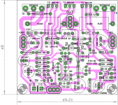
here is a jumper-less version based on my earlier version. I am not able to find time😱.
reg
Prasi
Ok, Here are the pdf's for FH-9 by APEX-XRK 971 for anyone doing DIY. Sch is in previous pages by XRK.
reg
Prasi
Attachments

In fact one pair of lateral MOSFETs can easily run on +/-50V or even more. Elliott's P101 with one pair of lateral MOSFETs is designed to work at +/-56V (dual 40V secondaries transformer). P101 with two pairs is designed to work at +/-65-70V. Lateral MOSFETs are that robust! They have unique resilience to thermal runaway. Companies from UK are using them for 40 years exactly because that robustness and in most cases they even do not even require protection. It's very difficult to burn them even with prolonged hard work. But, of course, lower working voltages will provide almost absolute reliability in FX8 circuit.
I was going to let this go but I am worried that others will read this so I will ask you to read what Rod Elliot actually said.
Project 101 - High Power, High Fidelity Lateral MOSFET power amplifier
It is the high watt version using 2 pair that is recommended to use +-56V supply, although he say it will handle +-70V he recommends +-56V for the 2 pair version.If this version is built (using only 1 pair of MOSFETs), IMO it is essential to limit the supply voltage to ±42V so that it can drive both 4 and 8 ohm loads without excess dissipation.
IMO there is nothing to be gained from driving one pair with more than +-42V.
Why are you trying to run a single pair at 50v? Do you really believe you will hear the extra dB or two? All you're going to get is stressed devices for very little gain.
IRF type mosfet indeed needs higher voltage (the drive side) than BJT or even latfet. Will we hear the extra dBs? Most probably yes. It is still a mystery to me regarding the psychological perception of high power (too many variables involved). So the voltage increase might "make or break".
In term of sound quality, it is more possible that the performance of a transistor is optimum when it is operated close to it's maximum capability. The problem is only with safety. It is not easy to predict the security as a good transistor may perform well above its published spec and poor ones may perform worse.
For input transistors, I think I have never seen a thermal runaway. Vce of the transistor should be selected carefully. For VAS or current stage the risk is higher. Replacement to the BD139 has been suggested before. BD139 has Vce of 80V. For good safety factor, maximum of 40V is usually recommended. Power/heat is another issue. Adding heatsink even if it runs cool could be done to increase safety factor.
For the output itself, I think most IRF mosfet have high current capability, thus the problem is with thermal runaway (second break down). You can do the Math (use 2R load) but I think there's no sign of danger with 50V for an IRF as long as thermal compensation is done and there is sufficient heatsink.
so how does one calculate what rail voltages are needed for a class AB? I currently have 35v rails - will that be enough?
Is 5W enough? It is for those with Lowther and SE triode amps! So 35V rails with sufficient current capability (big transformer) should be much louder 😀
I don't know, but from experience, I have always tried to make class AB amps to have a minimum of 60W. It is usually a "threshold" where in many situations I can start to feel the "power".
I think I may try it out with a 50v supply and see if I hear a difference. Those IRFPs are indeed designed to be run with higher voltages and handle a lot of current. If I get with some 10ohm rail safety resistors first it may be an OK first step. Worst case is I might melt a BD149/140 or IRFP's. I don't think so though. We will see but won't be for maybe another week.
Ok, Here are the pdf's for FH-9 by APEX-XRK 971 for anyone doing DIY. Sch is in previous pages by XRK.
reg
Prasi
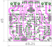
Nice work, can you move VAS transistors closer to BIAS transistor?
Regards
I was going to let this go but I am worried that others will read this so I will ask you to read what Rod Elliot actually said.
Project 101 - High Power, High Fidelity Lateral MOSFET power amplifier
It is the high watt version using 2 pair that is recommended to use +-56V supply, although he say it will handle +-70V he recommends +-56V for the 2 pair version.
IMO there is nothing to be gained from driving one pair with more than +-42V.
Obviously he changed recommendations in the text, probably recently. This is the text that was on his site when I built P101:
Low Power Version
As shown in the schematics below (figures 1 and 2), the amplifier can be made in high or low power version, and although there is a bit of vacant PCB real estate in the low power design, it is significantly cheaper to make and will be more than sufficient for most constructors. If this version is built (using only 1 pair of MOSFETs), it is essential to limit the supply voltage to +/-56V so that it can drive both 4 and 8 ohm loads without excess dissipation. With this voltage, expect about 100W continuous into 8 ohms, and around 150W into 4 ohms. Naturally, dual MOSFET pairs may be used at this voltage as well, providing much better thermal performance (and therefore cooler operation), far greater peak current capability and slightly higher power. This version may be used at any voltage from +/-25V to +/-56V.
High Power Version
The same PCB is used, but has an extra pair of MOSFETs. Since the devices are running in parallel, source resistors are used to force current sharing. Although these may be replaced by wire links, I do not recommend this. This version may be operated at a maximum supply voltage of +/-70V, and will give up to 180W RMS into 8 ohms, and 250W into 4 ohms. Short term (peak) power is around 240W into 8 ohms and 380W into 4 ohms. These figures are very much dependent on your power supply regulation, determined by the VA rating of the transformer, size of filter caps, etc.
Nice work, can you move VAS transistors closer to BIAS transistor?
Regards
Done, Mr. Mile.
regards
Prasi
Attachments
Obviously he changed recommendations in the text, probably recently. This is the text that was on his site when I built P101:
Low Power Version
As shown in the schematics below (figures 1 and 2), the amplifier can be made in high or low power version, and although there is a bit of vacant PCB real estate in the low power design, it is significantly cheaper to make and will be more than sufficient for most constructors. If this version is built (using only 1 pair of MOSFETs), it is essential to limit the supply voltage to +/-56V so that it can drive both 4 and 8 ohm loads without excess dissipation. With this voltage, expect about 100W continuous into 8 ohms, and around 150W into 4 ohms. Naturally, dual MOSFET pairs may be used at this voltage as well, providing much better thermal performance (and therefore cooler operation), far greater peak current capability and slightly higher power. This version may be used at any voltage from +/-25V to +/-56V.
High Power Version
The same PCB is used, but has an extra pair of MOSFETs. Since the devices are running in parallel, source resistors are used to force current sharing. Although these may be replaced by wire links, I do not recommend this. This version may be operated at a maximum supply voltage of +/-70V, and will give up to 180W RMS into 8 ohms, and 250W into 4 ohms. Short term (peak) power is around 240W into 8 ohms and 380W into 4 ohms. These figures are very much dependent on your power supply regulation, determined by the VA rating of the transformer, size of filter caps, etc.
If he changed the verbiage it is likely because it was determined the +-56v was putting too much stress on the outputs. I warned against using the high voltage/high bias for the benefit of other newbies who may be reading this thread. xrk971 already has his mind made up and just wanted to find someone who would agree with him. Will he get away with running things that high? Likely for a while. That doesn't mean it is sound practice.
I warned against using the high voltage/high bias for the benefit of other newbies who may be reading this thread. xrk971 already has his mind made up and just wanted to find someone who would agree with him. Will he get away with running things that high? Likely for a while. That doesn't mean it is sound practice.
I heard your warnings and was going to use at 35v for actual listening. However I just want to test it with 49v on the vertical IRFP FETs. My usual one is 35v which is fine for long term use. I am just curious.
Gerbers.
Hi Prasi,
Can you post the Gerbers for your FH-9 board?
Thanks...
Done, Mr. Mile.
regards
Prasi
Hi Prasi,
Can you post the Gerbers for your FH-9 board?
Thanks...
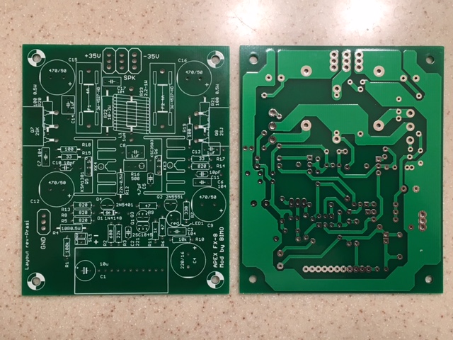
Thank you for the nice layout Prasi. Yes, Gerbers would be nice - it probably has been reviewed and refined enough at this point especially if the last comment from Apex was just to move the VAS over to the middle. 🙂
Guess I will be ordering up some more boards. If it's not too much trouble can you put the Apex FH9 label on it somewhere?
Thanks,
X
Guess I will be ordering up some more boards. If it's not too much trouble can you put the Apex FH9 label on it somewhere?
Thanks,
X
Thank you for the nice layout Prasi. Yes, Gerbers would be nice - it probably has been reviewed and refined enough at this point especially if the last comment from Apex was just to move the VAS over to the middle. 🙂
Guess I will be ordering up some more boards. If it's not too much trouble can you put the Apex FH9 label on it somewhere?
Thanks,
X
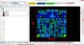
Pl find attached the gerbers for FH-9. I had already put a label on silk, "FH-9 APEX-XRK"
Do you want me to put something else?
reg
Prasi
Attachments

- Home
- Amplifiers
- Solid State
- 100W Ultimate Fidelity Amplifier