Hi Gaborbela, Do look back at your original thread. I did try your circuit with bipolar output and Lat FET outputs. I reported the results there. The bipolar with stable bias was also tried and it worked well. An additional resistor was used in the bias circuit. Go back to the thread ! Stable at 100mA bias ! However it didn't need that much bias to sound very good.
Very good sound from that circuit. Lat FET seemed slightly light weight compared to the bipolar's but had a slightly crisper HF. Not a large difference but if you listened very carefully with a good recording , you can hear it.
I started on a board with higher supply rails but haven't yet got round to it. I think it sounds better than several other amps I have around here.
Hi ashok
I mention I try to avoid Lat Fet with that circuit especially the Renesans type. May be EXICON type.
To me they have way to soft bass several circuit I used them, with these I never tested) SORRY 😕
That project somehow stopped - several people was interested including me For a while I was sick, just got cortisone into my left shoulder. Now I feel better so I want to do something with that. I missed that amplifier!!!
The best sound I ever got my own system with the mentioned (recommended) semiconductors.
If we talk about mosfet I'm more open to use Toshiba 2SK1529 & 2SJ200..
The truth is I had several project with Hitachi Lat Fet and always I missed something in the bass area.
That not mean these can not sound good PECEBE and VSSA very close to that project if I will use Lat Fet.
Terry here is it
Read the last 20-30 pages
http://www.diyaudio.com/forums/solid-state/133189-my-first-diy-amplifier-20-years-go-59.html
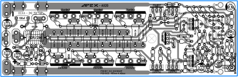
My AX-14
Very nice PCB Willy, your pcb motivated me to work on AX20 with 3 pair OP.
Regards
Sonal Kunal
Attachments

AX-20 with 3 pair OP.
very very nice sonal!
reg
prasi
P.S. you have convinced me to learn sprint!!. but I am an old dog, lets see if I can learn new tricks..
Hi,
Very very nice Sonal,You are turning out to be our own Indian version of AlexMM !! This reminds of him greatly (very very similar layout style). Glad to have you amongst us.
After a really long time I just Am in a process of completing the AX-14 Amp,Here's the work in progress so far !
Yesterday bought all the components but the MJ15003 turned out to be a fake,so have to return them back and try to get original one's,They are so damn hard to come by !!
Anyways wish me luck guys,also any pointers to keep in mind before turning it on.


Regards.
AX-20 with 3 pair OP.
Very very nice Sonal,You are turning out to be our own Indian version of AlexMM !! This reminds of him greatly (very very similar layout style). Glad to have you amongst us.
After a really long time I just Am in a process of completing the AX-14 Amp,Here's the work in progress so far !
Yesterday bought all the components but the MJ15003 turned out to be a fake,so have to return them back and try to get original one's,They are so damn hard to come by !!
Anyways wish me luck guys,also any pointers to keep in mind before turning it on.
Regards.
After a really long time I just Am in a process of completing the AX-14 Amp, Here's the work in progress so far !
Yesterday bought all the components but the MJ15003 turned out to be a fake,so have to return them back and try to get original one's,They are so damn hard to come by !!
Anyways wish me luck guys,also any pointers to keep in mind before turning it on.
Regards.
Nice work!!!
-MJE340/350 in VAS needs small heatsink, for keeping thermal noise lowest possible,
and they run pretty warm (60°C+) with 0,5-1W/each thermal dissipation
-insert max 1A fusses
-connect in series with PSU rails 15-20R/several watts (15-20W),
don`t supply the amp directly!
This resistor is here for PSU current limiting,
-turn Bias trimmpot P1 to achieve max resistance,
you will start running the amp in the classB region with almost zero bias current
-short input to SigGND
-connect at SpkOUT 8R0/(10-20W) dummy load
----------------
Good luck SoundsGreat: 🙂
-Power on
-IF the fusses don`t blow up,
-THEN measure with DMM DC voltage drop on 15R/20W resistors on the supply's,
the drop must be below 0,3-0,5VDC (cca 20mADC+)
-control output DC voltage +/-10-15mVDC is OK
-increase P1 slowly to achieve a voltage drop at 0R33 output emitter resistor cca 16-17mVDC
(min 50mADC Bias/pair)
-wait for warm up 10-15min
-control output DC voltage
-control Bias current (re-adjust if needed)
-control with your fingers (better with TermMeter 🙂 )
that also thermal dissipation for each element on the PCB is under normal conditions (max 50°C)
-Power off
-wait that PSU voltages drop near 0VDC
-eliminate input short
-eliminate PSU rail additional resistors
-insert rated fusses
-connect Speaker
-connect input signal (music source with volume control)
-Power on
Enjoy!
🙂
--------------------
-ELSE: (if fusses 1A blows up or voltage drop on PSU rail resistors are excessive)
-re-check elements, values, PCB traces, soldering,
...measure nodal voltages and post here
LP
Dragan
The board look nice SoundsGreat I see that components fits really well 🙂 good luck bro !
Regard
Juan
Regard
Juan
Hi,
Juan its all big thanks to you,without your support it wouldn't have been possible 😎! Indeed everything fits well and Hope sounds well too.I wanted to post a special thank you message but in rush to head to electronic market I just missed it out ! None the less I wholeheartedly thank you for all the help (might need some more too,for which I will mail you).
Update : The whole of my local electronic market is out of MJ15003 😡 ( or have fakes),So had to settle for 5200/1943 for now to test the boards for proper working. What are the major changes that I can expect with these 😛 ??
Dragon,God bless you my dear friend for you are a god send !! You have given very invaluable help,I was generally looking for some basic do's and dont's but you given a complete and most in depth starting guide (so to speak), So thanks a million for your help 😀 !
Just one thing I want to ask,I had asked this question before to Mr.Mile as well.
I want the Amp to run in Class A for few watts before switching to A/B ( I will have a big heat sink when I build my cabinet ),So what would be the ideal Bias that I set to achieve it and for how many watts can I expect this run in Class A ?? (I have my rudimentary calculations but want an thorough answer ).
Off course none of this would've ever been possible without Mr.Mile's circuits and guidance,So Thanks to you too Mr.Mile for all the help and support.
Have finished the assembly of all the parts,Will begin the testing process soon,Will update accordingly !
Regards.
The board look nice SoundsGreat I see that components fits really well good luck bro !
Juan its all big thanks to you,without your support it wouldn't have been possible 😎! Indeed everything fits well and Hope sounds well too.I wanted to post a special thank you message but in rush to head to electronic market I just missed it out ! None the less I wholeheartedly thank you for all the help (might need some more too,for which I will mail you).
Update : The whole of my local electronic market is out of MJ15003 😡 ( or have fakes),So had to settle for 5200/1943 for now to test the boards for proper working. What are the major changes that I can expect with these 😛 ??
Dragon,God bless you my dear friend for you are a god send !! You have given very invaluable help,I was generally looking for some basic do's and dont's but you given a complete and most in depth starting guide (so to speak), So thanks a million for your help 😀 !
Just one thing I want to ask,I had asked this question before to Mr.Mile as well.
I want the Amp to run in Class A for few watts before switching to A/B ( I will have a big heat sink when I build my cabinet ),So what would be the ideal Bias that I set to achieve it and for how many watts can I expect this run in Class A ?? (I have my rudimentary calculations but want an thorough answer ).
Off course none of this would've ever been possible without Mr.Mile's circuits and guidance,So Thanks to you too Mr.Mile for all the help and support.
Have finished the assembly of all the parts,Will begin the testing process soon,Will update accordingly !
Regards.
For a few watts of ClassA you need a big output bias.
eg.
1W of ClassA into 8ohms is equivalent to 4Vpk and 500mApk into 8r0 test load.
A total output bias of 255mA will allow you to drive that 8r0 test load to 1W of ClassA before transitioning to ClassAB.
5W of ClassA would require 565mA of output bias.
A 5pair output stage with 0r22 emitters resistors set to optimal ClassAB bias of 26mVre will have a total 590mA and just exceed a 5W ClassA target.
But optimal ClassAB bias for a 0r22 emitter resistor may turn out to be <<26mVre.
You may have to reduce the emitter resistors to 0r18, or even 0r15, to hit the optimal ClassAB and hit the 5W target.
For classA push-pull topology current limitation:
2x I_bias TOT = I_out_peak = max classA output peak current
if upper output device reach (2x I_bias, or just 1mA less) in positive amplitude
the lower output device is just close to be closed (no more conductive)
and furthermore with increasing output current, the output stage leaves the classA region,
then it works in classB to the limitations of topology and/or PSU rail voltages and/or current PSU capability
the push-pull output stage (both devices - pair) is no more conductive in all four quadrants at the same time,
or can`t achieve 360° or 2*PI radians, and this is the definition of classA push-pull operandum.
AndrewT give you a very neat example!
You must consider that output stage thermal dissipation is a bit high operated in class A
With 2 pairs of MJ15003/4 TO3 250W in output stage you can achieve 200WRMS+ of output power @ 8R0
for that you need cca +/- 60-65VDC PSU rails
or even +/- 70VDC with triple emitter follower output topology.
With 1943/5200 150W devices, max 120WRMS / 8R0 with +/-45 - 50VDC PSU or +/-55VDC with TEF.
Your goal is achived 5WRMS / 8R0
(not RMS, voltages and currents are RMS, power is V_RMS*I_RMS=P_AVARAGE, but all around is in use RMS! 🙂 )
For that you must bias the output stage with min 560-565mA or 280mA+ each output pair.
With +/- 65VDC rails and 560-565mA bias, we have 73-75W of the thermal dissipation / channel,
and yes, ideal for winter months!
If your heatsink can deal with such a therm. dissipation, then is OK,
else go with a smaller bias portion and check the heatsink temperature!!!
(max 50-55°C with only Bias current )
Lp
Dragan
Last edited:
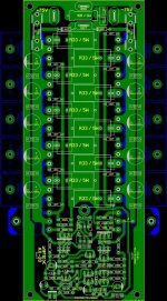
Hi sir willjj78 pls share ax20 5pair output pcb layout copper side files
Noted, will upload and share you that shortly..
Regards,
Noted, will upload and share you that shortly..
Regards,
Hi sir wiljj78.
Thanks for your quick reply.
this question is for willyjj. isnt the i/p track a little too close to o/p track on left?Hello Willy
greetings can you share SPRINT LAY file for this pcb
warm regards
Andrew
reg
prasi
Hi,
Andrew & Dragon thanks to both of you for help. As mentioned I can go for a bigger than usual heatsink but not to the extent of a true Class A type.
Will test it for now and then take it forward.
Regards.
Andrew & Dragon thanks to both of you for help. As mentioned I can go for a bigger than usual heatsink but not to the extent of a true Class A type.
Will test it for now and then take it forward.
Regards.
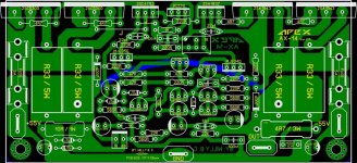
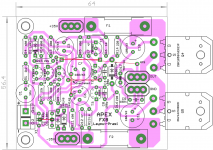
There is FX8
Mr.Miles,
Here is an idea for Fx8 layout. Very compact, but I am not entirely satisfied with number of jumpers. Can you suggest improvements? I have added fuses and bypass caps.🙂. minimum 20mils spacing , dont know if its good enough for iron transfer, but enough for phtoresist.
reg
Prasi
Attachments
- Home
- Amplifiers
- Solid State
- 100W Ultimate Fidelity Amplifier