Terry,
what are the small oval yellow caps you use in the fx100?...ceramic?
thanks,
freeman
Yes, Multilayer Monolithic Ceramic Capacitor.
Someone who can make a pcb for this protection circuit?
Hello thimios,
I think PCB for this protect is already shared by cbm08, if I am not mistaken.
Reg
Prasi
Hello thimios,
I think PCB for this protect is already shared by cbm08, if I am not mistaken.
Reg
Prasi
I thought that too but when I compared the schematics they are slightly different.
can someone recommend zeners for the fx100 amp? zy15 and zl12 appear to be obsolete. are 1n4744 and 1n4742 ok? thanks.
can someone recommend zeners for the fx100 amp? zy15 and zl12 appear to be obsolete. are 1n4744 and 1n4742 ok? thanks.
I think zy15 is for 2w 15v and zf12 is for 0.5w 12v.
No this is from a previous schematic.Hello thimios,
I think PCB for this protect is already shared by cbm08, if I am not mistaken.
Reg
Prasi
question for eagle users
hi all,
im leaning toward purchase of sprint-layout because of ease of creating iron transfer file. how easy is iron transfer in eagle? thanks.
hi all,
im leaning toward purchase of sprint-layout because of ease of creating iron transfer file. how easy is iron transfer in eagle? thanks.
Apex,
I reflowed all tracks and did some measurements and this is what i came with. i also replace bias resistor just in case it was defective but it was good. all this measurements are with no load, inputs shorted.
I reflowed all tracks and did some measurements and this is what i came with. i also replace bias resistor just in case it was defective but it was good. all this measurements are with no load, inputs shorted.
An externally hosted image should be here but it was not working when we last tested it.
Last edited:
Apex,
I reflowed all tracks and did some measurements and this is what i came with. i also replace bias resistor just in case it was defective but it was good. all this measurements are with no load, inputs shorted.
An externally hosted image should be here but it was not working when we last tested it.
I inputted your rail voltages into my spice file and here are the voltages you should see.
Attachments
Apex,
I reflowed all tracks and did some measurements and this is what i came with. i also replace bias resistor just in case it was defective but it was good. all this measurements are with no load, inputs shorted.
An externally hosted image should be here but it was not working when we last tested it.
Check R20, R21 and Q11
the schematic i posted was from the first post but the placement on the PCB is correct. Replaced R20, R21 and Q11, same outcome. did diode test on q11 after removed and it seems good. I will apreciate all the help.Quote:
Originally Posted by Dacz View Post
r2 and r8 reverse?
yes
the schematic i posted was from the first post but the placement on the PCB is correct. Replaced R20, R21 and Q11, same outcome. did diode test on q11 after removed and it seems good. I will apreciate all the help.
first remove the 104 cap and direct short the sgnd with psu gnd and then measure .if you make own pcb then pcb is faulty and if you made on thread pcb then any component and polarity issue.
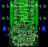
TIDU with APEX shunt supply, thanks to dragan 100 and Mr. Miles🙂... Untested... what needs to change on supply PCB for 15V suitable for opa 1604 (I just changed zener to 15V).
reg
Prasi
P.S. chinese pirates😀!!!
Nice work, 15V zener is OK.
Regards
- Home
- Amplifiers
- Solid State
- 100W Ultimate Fidelity Amplifier