This is the output stage on apex 100 W amplifier with current protection /short circuit/
what do you think ?
Тoday I solder protection under this circuit and everything works.
I short output and nothing burns 😉
http://www.diyaudio.com/forums/atta...w-ultimate-fidelity-amplifier-100wprotect.jpg
Last edited:
on AX 14 Amplifier, what happens to the distortion if Q6 and Q8 ( VAS Stage) are replaced with an irf610 mosfet with 7.5v gate protect zener where D1 is

 nice !
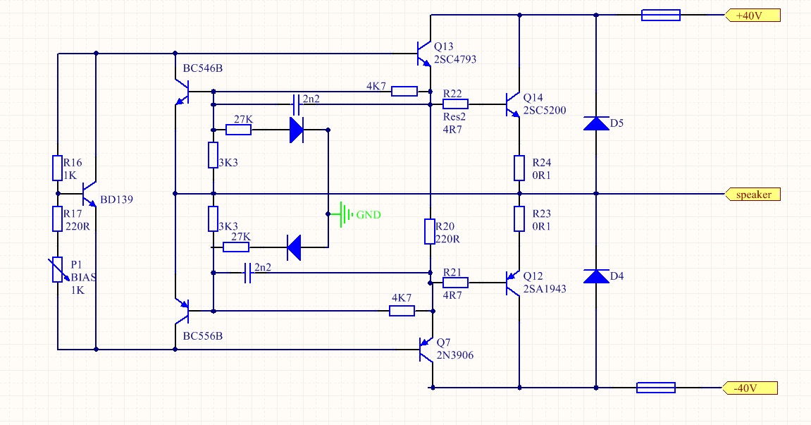
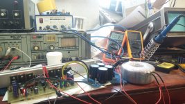
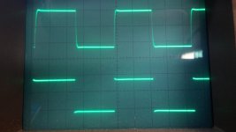
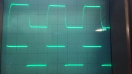
So I finally revived A40 .. square at 20khz and 50khz...very clear sound with good bass..
Nice work, regards.
Thanks guys...so, I have to make some chassis...I gonna also use my two 300VAC transformers with 29AC.. I hope that will be enough.
Calculate it.
29Vac gives ~ 1.4*29 as your loaded DC voltage, i.e. around 40Vdc
two times 29Vac gives around +-40Vdc when loaded.
Assume 4V lost through the amplifier when delivering maximum power.
i.e. maximum output ~35Vpk
Maximum power = Vpk²/Rload/2
i.e. 35²/8/2 = ~76W into 8r0 dummy load. If you build the PSU and amplifier properly.
Ok .... @AndrewT, thanks for explaining, as PSU for this amplifier I have bought two toroidal transformers (45VAC - 200W for each channel). All i need is time to build it. @ maxwell007 how is bias adjustment? It's easy? Did you encountered problems?
Regards Dan.
Regards Dan.
I have run this amp between +-25vdc and +-50vdc. +-50vdc is pushing it for 4ohm. 45-0-45vac is way too much for this amp.
I had problems just with my own stupidity 🙂 one short, and substitution BC.. there is no problem with build and setting...
I have the possibility to change the transformers twith two toroidals (2x40VAC, 200W/ channel). The speakers are 8 ohms impedance......
Hi Daniel,
I didn't see which amp you are building. 40-0-40vac transformer will give about +-56V unloaded so about +- 52-54vdc rails. Too much for one pair of output transistors. You need to build one of the ones with at least two pairs.
I didn't see which amp you are building. 40-0-40vac transformer will give about +-56V unloaded so about +- 52-54vdc rails. Too much for one pair of output transistors. You need to build one of the ones with at least two pairs.
Sorry...., the amp in discussion is A40, with the layout made by @Alex. Thank's for the advices @still4given .
Regards.
Regards.
So, I found some 2x36V 300VAC transformers....it will be +-50v and i hope that will be enough...It should be cca 130W to 8r..
- Home
- Amplifiers
- Solid State
- 100W Ultimate Fidelity Amplifier