@kandimba, please place the specs for the transformers you're gonna order (V, VA).
Your PCB layout in pdf format would be very welcome as well.
Tnx.
Your PCB layout in pdf format would be very welcome as well.
Tnx.
Last edited:
@kandimba, please place the specs for the transformers you're gonna order (V, VA).
Your PCB layout in pdf format would be very welcome as well.
Tnx.
I agree.

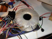
My first Apex AX20 channel was tested with transformer from a burnt Inter-M L2400 amplifier, as you can see in the picture, this transformer is good to feed the Apex H900. But for my AX 20 stereo amplifier I gona use 1000 VA. About PCB layout, no problem, here is for those wants do de some amplifier. You should star doing the protection first and teste it, than the amplifier, try to avoid component mistakes and dont forget de diferent grounds (in ground and normal ground). And we should say thanks to Miles Boss 🙂
Regards
Regards
Attachments

My first Apex AX20 channel was tested with transformer from a burnt Inter-M L2400 amplifier, as you can see in the picture, this transformer is good to feed the Apex H900. But for my AX 20 stereo amplifier I gona use 1000 VA. About PCB layout, no problem, here is for those wants do de some amplifier. You should star doing the protection first and teste it, than the amplifier, try to avoid component mistakes and dont forget de diferent grounds (in ground and normal ground). And we should say thanks to Miles Boss 🙂
Regards
Thank you for pdf files,
Regards
Miniamp, very good sound. Thanks apexaudio and borys.
Nice work, AX11 is my favorite miniamp,
Regards
Dear Mile,
Can I use this stereo protect for 2x AX 16/20?
Would it pro working if i parallel 2 amp like in my attachment?
Yes,
Regards
AX17
I have simulated the AX17 schematic in LTSpice, but I obtain poor THD results, 0.18% at 10khz 1V input.
What can be done to increase the performance of this schematic?
Have somebody measured real THD after building this amplifier? what were the results?
See attached files.
Thanks
I have simulated the AX17 schematic in LTSpice, but I obtain poor THD results, 0.18% at 10khz 1V input.
What can be done to increase the performance of this schematic?
Have somebody measured real THD after building this amplifier? what were the results?
See attached files.
Thanks
Attachments
post your asc file. Some sim expert/s can look at how you implemented the THD question.
It is posted there, look more carefully.
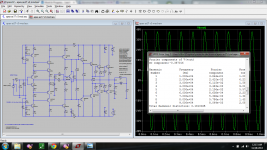
Here is a new one, with minor changes that lead to 20x less THD, and has -91deg in LoopGain, so it should be perfectly stable (-91 + 180 = 89deg).
Is it correct and better than the original one?
Attachments
Last edited:
It is posted there, look more carefully.
Here is a new one, with minor changes that lead to 20x less THD, and has -91deg in LoopGain, so it should be perfectly stable (-91 + 180 = 89deg).
Is it correct and better than the original one?
It's correct, nice work thanks.
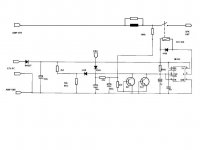
A few more images: schematic, thd, loopgain.
THD is strongly dependent on the chosen VAS transistors, these
2SA1381/2SC3503 with aprox 5mA collector current obtain the best results in simulator.
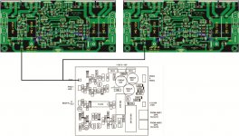
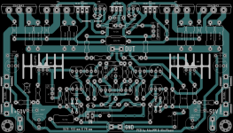
I have also prepaired a PCB layout for this AX17 schematic with two pairs of output transistors.
THD is strongly dependent on the chosen VAS transistors, these
2SA1381/2SC3503 with aprox 5mA collector current obtain the best results in simulator.
I have also prepaired a PCB layout for this AX17 schematic with two pairs of output transistors.
Attachments
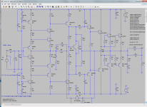
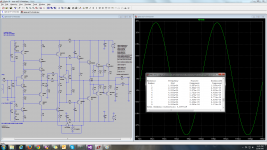
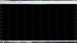
A few more images: schematic, thd, loopgain.
THD is strongly dependent on the chosen VAS transistors, these
2SA1381/2SC3503 with aprox 5mA collector current obtain the best results in simulator.
I have also prepaired a PCB layout for this AX17 schematic with two pairs of output transistors.
There is many better VAS transistors than MJE340/350 but MJEs are easy available. Would you share your pcb?
AX17
Here is the PCB for this AX17 schematic with two pairs of output transistors.
It is an extended version of the one firstly designed by AlexMM.
A double check across the schematic should be performed. Note that the components' numbers on my LTSpice schematic do not match the original numbering, please check considering their values only.
I will provide bottom copper layer pdf file in Private Message for those interested in building it.
Any suggestions for improving the PCB and/or schematic are welcome.
Regards
http://i1012.photobucket.com/albums/af241/vlasin_alin/apexAX17_v3_zpsffe74902.png~original
Last edited:
- Home
- Amplifiers
- Solid State
- 100W Ultimate Fidelity Amplifier