The 10 Ohm resistor and 10uH choke is (or should be) part of the amplifier. The choke is an "build-out" impedance that prevents the speaker cable from shorting the amplifier feedback at high frequencies and making the amp oscillate. The 10 Ohm resistor is a damper for the choke, that prevents the choke from ringing at it's resonant frequency. The current path for audio frequencies is though the choke, not the resistor.
Thanks for quick response.The 10 Ohm resistor and 10uH choke is (or should be) part of the amplifier. The choke is an "build-out" impedance that prevents the speaker cable from shorting the amplifier feedback at high frequencies and making the amp oscillate. The 10 Ohm resistor is a damper for the choke, that prevents the choke from ringing at it's resonant frequency. The current path for audio frequencies is though the choke, not the resistor.
i decide to buy finish product i will put this protection in my 2 channel amp.
UPC1237 30A High Power Stereo Speaker Protection Board OMRON Relay AC 12V-16V | eBay
those relays on protection from link you have shared are the best one I could find for this purpose,without too high price tagged on. I use on my protections same type but other manufacturer. as far as I could say-good choice! good luck with project!
I have not trawled through all of this thread, but I can't believe this circuit will work well. The protection transistors are shown in post #1 with 1uF capacitors between C&B. Surely, these will try to clamp the signal from the drivers under normal use?

Is 500ohm dc setting?
Regards
Gurpreet
Yes output DC offset setting.
Oh, sorry.
Hello Olaf,
Thank you for the sch. I know its been quite some time you built it, but Could you please tell me how to set it up it for different power amps, for e.g. 60W-8R amp or 200W-4R amp. Also is there a possibility to use 12VDC supply?
regards
Prasi
A 60W@8Ohm amp will have a power supply that is +/-(3+sqrt(60*8*2) or about +/-34VDC.
So for 200W@4 you need +/-(3+sqrt(200*4*2) ie about +/- 43VDC.
A 12VDC supply requires an inverter, and you are better off buying an auto bass amp with a built in inverter. Note that Auto amps are made for about 1 Ohm, ie much less power into 4 or 8 Ohms.
So for 200W@4 you need +/-(3+sqrt(200*4*2) ie about +/- 43VDC.
A 12VDC supply requires an inverter, and you are better off buying an auto bass amp with a built in inverter. Note that Auto amps are made for about 1 Ohm, ie much less power into 4 or 8 Ohms.
Hello Olaf,
Thank you for the sch. I know its been quite some time you built it, but Could you please tell me how to set it up it for different power amps, for e.g. 60W-8R amp or 200W-4R amp. Also is there a possibility to use 12VDC supply?
regards
Prasi
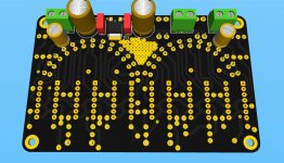
something like this on the front panel, with dark plexi glass for a 55W amp🙂. still in the rough stages....
Attachments
Hello I am asking about the lm334 vu meter that olaf built. see quoted post!
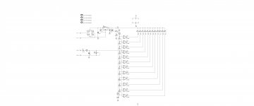
For LM339 vu meter use 7805 with heatsink to get +5V from 12V psu, and 10k pot instead 4k7 resistor to set full scale whan amp clip.
Hi,
if I remember correctly, that's vu-meter is made for line-level. So it works for any Amp. For 12V you probably need resistors for the LED's and another resistor for the Zener. The resistor chain forms the reference voltages for the comparators, which then either drives the LEDs or not. Works fine.
regards Olaf
For LM339 vu meter use 7805 with heatsink to get +5V from 12V psu, and 10k pot instead 4k7 resistor to set full scale whan amp clip.
Thank you Mr. Miles,
Do you mean connection like this?
Attachments
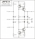
The two Zener diodes set the rail voltage. The two transistors form a 'ring of two' current regulator.
The maximum current flow in the Zener is 0.65 (transistor vbe) divided by the 22 ohm. That means approx. 30 milliamp flows in each Zener.
The maximum load current that can be drawn is 30 milliamp less a small fixed Zener current. So the circuit can power loads needing approx. 0 to 25 milliamps.
Always calculate the off load power dissipation in the Zener and the power dissipation in the series pass transistor. In this case the Zener power dissipation is 0.03 * 18 which is 0.54 watt. So a 1 watt part is needed.
The transistor dissipation is (110-18) * 0.03 which is 2.76 watt. A small heatsink would be needed for each pass transistor.
Thanks for your explanation. How do we calculate the values of other two resistors?
Regards,
Sumesh
Regards,
Sumesh
The two Zener diodes set the rail voltage. The two transistors form a 'ring of two' current regulator.
The maximum current flow in the Zener is 0.65 (transistor vbe) divided by the 22 ohm. That means approx. 30 milliamp flows in each Zener.
The maximum load current that can be drawn is 30 milliamp less a small fixed Zener current. So the circuit can power loads needing approx. 0 to 25 milliamps.
Always calculate the off load power dissipation in the Zener and the power dissipation in the series pass transistor. In this case the Zener power dissipation is 0.03 * 18 which is 0.54 watt. So a 1 watt part is needed.
The transistor dissipation is (110-18) * 0.03 which is 2.76 watt. A small heatsink would be needed for each pass transistor.
The 22k's need to allow sufficient base current to flow in order to allow the series pass transistor to turn on hard enough to deliver the load current.
The voltage across the 22k is equal to the supply minus the two 0.65 volt B-E volt drops of the two transistors. For supply voltages over 10 volts we can disregard these and simply say that the 22k resistor will see the full supply, 110 volts in this case.
The gain of the transistor determines how much base current we need.
We know are current source can only deliver 30 milliamps (because of the 0.65v across the 22ohm) and so given an approximate DC current gain for the pass transistor we can work back. The data sheet for the 2SA1837 says DC current gain can be from 100 to 320.
Pick the lower value or 100 and divide the 30 milliamps by that. This gives 0.3 milliamp.
The required resistor would be 110 (voltage across the resistor) divided by required current (0.3 milliamps) which is 366k
Why has the designer chosen 22k ?
We play safe to ensure it will work under all possible conditions, perhaps in temperatures as low as -25C and perhaps with lesser specced (lower gain parts).
Normally I would go for something like an 82k resistor in a situation like this and for that particular part. That's decreased the calculated value by a factor of four and ensures any device of that type will work correctly under any possible usage condition for this particular circuit.
Based on the above, the 22k seems excessively low to me, and as a consequence dissipates more heat than we need.
Wattage of the resistor needs to be (110*110)/R which for an 82k would mean a 0.14w rated part. Again, for reliability we would choose a larger part, perhaps a 0.5 watt.
- Home
- Amplifiers
- Solid State
- 1000W Simple PA Amplifier