The 22k's need to allow sufficient base current to flow in order to allow the series pass transistor to turn on hard enough to deliver the load current.
The voltage across the 22k is equal to the supply minus the two 0.65 volt B-E volt drops of the two transistors. For supply voltages over 10 volts we can disregard these and simply say that the 22k resistor will see the full supply, 110 volts in this case.
The gain of the transistor determines how much base current we need.
We know are current source can only deliver 30 milliamps (because of the 0.65v across the 22ohm) and so given an approximate DC current gain for the pass transistor we can work back. The data sheet for the 2SA1837 says DC current gain can be from 100 to 320.
Pick the lower value or 100 and divide the 30 milliamps by that. This gives 0.3 milliamp.
The required resistor would be 110 (voltage across the resistor) divided by required current (0.3 milliamps) which is 366k
Why has the designer chosen 22k ?
We play safe to ensure it will work under all possible conditions, perhaps in temperatures as low as -25C and perhaps with lesser specced (lower gain parts).
Normally I would go for something like an 82k resistor in a situation like this and for that particular part. That's decreased the calculated value by a factor of four and ensures any device of that type will work correctly under any possible usage condition for this particular circuit.
Based on the above, the 22k seems excessively low to me, and as a consequence dissipates more heat than we need.
Wattage of the resistor needs to be (110*110)/R which for an 82k would mean a 0.14w rated part. Again, for reliability we would choose a larger part, perhaps a 0.5 watt.
There is 45V voltage drop on 1k5 resistor, you must calculate with 65V instead 110V rail voltage.
My apologies, I honestly hadn't spotted that resistor... it just didn't register for some reason.
Yes, that will ease the dissipation of the series pass transistor and make the 22k more realistic.
Yes, that will ease the dissipation of the series pass transistor and make the 22k more realistic.
May I have a Apex B2000 pcb layout please?, gerber files, etc, anything please, thx in advance.
BA2000 pcb not tested
sir, please post copper side pdf tofor pcb so that we can make it.
BA2000 pcb not tested
Sir miles please post updated schematics of BA2000 thanks
hi friends,
i have to ask some thing. can i make this amplifier with what i have.
1. can i keep going with 2sc5200 and 2sa1943 for mjl4281 and mjl4302. cause i have 12/12 of them and i dont want they go trash 🙁(
2. that 5w 1R resistors if i use my power transistors can i use 0R47 5w resistors?
3. can i use 2n5551 and 2n5401 for bc337 and bc327 ?
4. i just have 90vdc + - . is it ok for this amp? its coming from 1000w old amp transformer.
5. what is D1 zy15?
6. what is the voltage for C1, C4, C5, C14 and C15
Last edited:
hi friends please help. 90v + - dc and can i use 2sc5200 and 2sa1943?
may i suggest you to try BA1200 with 8 or 9 pairs at least you have extra. 0.47R 5w resistors can be used but you have to adjust bias accordingly. another is your PSU can be used also. but not that BA2000 it was not tested and i saw some mistakes on PCB design. several diyers tried this BA2000 but they dont make it as easy to work with this BA1200.
sam
thank you Sam, i make b500. still have soma problems not working good. to day i will work on it some thing i cannot see but i dont know what is it. thank you for answer...
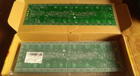
I have the BA2000 original amps PCB boards for sale. but double side.
If anyone need pls mail me shehanthapere@gmail.com
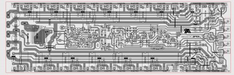
100% working and tested. Supper amp. if you build simply the pcb , ity wont work. Theres noise issues, so we need to follow the Original pcb design only
If anyone need pls mail me shehanthapere@gmail.com
100% working and tested. Supper amp. if you build simply the pcb , ity wont work. Theres noise issues, so we need to follow the Original pcb design only
I have the BA2000 original amps PCB boards for sale. but double side.
If anyone need pls mail me shehanthapere@gmail.com
100% working and tested. Supper amp. if you build simply the pcb , ity wont work. Theres noise issues, so we need to follow the Original pcb design only
well that's a very good news why not share your experience since you're the first one DIYer who made successful BA2000, can you show us some snapshot of your boards? thanks
regards
This Amplifier is simple class AB design for PA
It uses same front end as in the Hitachi lateral mosfet datasheet with additional of Vbe multiplier.
The Maplin lateral mosfet amplifier used that circuit too.
Low power version for fun.
Any one have PCB layout of BA100.
If yes please share
Regards
Gurpreet
Hello guys !
I'm going to make this 1000w amp.
I have find on this thread the amp board, the dc protect board, the input display board and the psu board.
Something is missing for my build ? A soft start or something like this ?
And, for the PSU, it's two transformers 38V-0V-38V in serie for an output of +110V/GND/-110V ... it's right ?
And if it's good, what is the rated VA for one of the two 38V transformers ?
Thanks a lot and sorry for my english
greetings sir RipX very nice pcb..do you have pdf file please share to us..thanks🙂
greetings sir RipX very nice pcb..do you have pdf file please share to us..thanks🙂
upon reading the whole thread i found out that the pcb that im asking is from sir wiljj78 design..im sorry sir wiljj78..my bad..
- Home
- Amplifiers
- Solid State
- 1000W Simple PA Amplifier