EWorkshop1708 said:It helps keep the CFP under control, Try the cap on both drivers, top and bottom, and then try a larger cap value, like 220pf or more. The output stage has more current than a VAS, the smaller cap values don't make as much difference with output stage.
Have you tried the larger zobel cap yet? 0.22 or 0.47uf?
I have taken a break from it for now. I'll resume tomorrow evening. My old friend "flux buildup" is happening again, and I need to clean it off. I stupidly still use plumbers flux, which is conductive, to make soldering easier. I'd really like a nice paste flux, that has no zinc in it and doesn't dry out when I leave the lid off.
Any ideas?
No I didn't change the Zobel cap yet. I think it's a 150nF anyway, since I don't have any 100nF polys left.
I am getting ahead of myself again. I really should be concentrating on the new front end design, and get that board done. I do know that eventually I'll get this amp to drive the 2 ohm load stable. In the meantime, it looks very good at 4 ohms and primo at 8.
megajocke said:I wouldn't call that ringing, ringing is to me something that happens around "sharp" edges.
Hi,
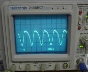
I was under the impression that full blown oscillation is different to what I have here. This looks like a stable amp driving a fairly big capacitive load. I have had oscillation before, on another amp at 1MHz (see pic below). It was a stand alone, wave form that didn't show in the amplified wave.
The output get hot and fail with this oscillation. My outputs with that (for want of a better term) ringing stay normally cool.
Attachments
I have flip-flopped again. I'm now back to bootstrap for the VAS and I have changed the schematic to suit.
Another thing I've changed is my selection for the VAS. The 2SA914 is a 50mA device, and I don't know if it will hold up well. The new configuration has the VAS running at ~10ma.
I went hunting for a suitable, high current, low Cob unit and the pickings are slim. The best candidate that I could find is the ZTX555 .
The only hiccup is it's an e-line package, so heatsinking would be a small problem.
I have decided to move the CFP drivers to the circuit board, along with base stoppers for the output stage. This will make the board a bit bigger, but may help with stability.
Attachments
Hi,
what about swapping the P & N outputs and making a darlington out of the drivers?
I prefer to see lower resistance values around the Vbe multiplier. 3k6>>1k8 and 1k0>>500r.
R7 must be scaled with the VAS current.
15r better suits 6 to 7mA.
10r to 12r for 10mA of VAS current.
what about swapping the P & N outputs and making a darlington out of the drivers?
I prefer to see lower resistance values around the Vbe multiplier. 3k6>>1k8 and 1k0>>500r.
R7 must be scaled with the VAS current.
15r better suits 6 to 7mA.
10r to 12r for 10mA of VAS current.
My suggestions to solve ringing problem:
1. Serial RC 470ohm and 470pF between collectors of Q4,Q5 helps to lower TIM and ringing on similar basis
2. Serial RC 100ohm and 470pF from collector Q1 to GND
3. 10-33pF parallel with R29
4. Remove R11 and R21, instead put only one 33ohm resistor between collectors of Q3 and Q12
5. Serial RC 2,2ohm and 1nF in parallel with R4, R34
Try with those, if still no progres I'll be in touch ... 😉
AndrewT said:Hi,
what about swapping the P & N outputs and making a darlington out of the drivers?
I prefer to see lower resistance values around the Vbe multiplier. 3k6>>1k8 and 1k0>>500r.
Hi Andrew,
The Vbe multiplier is the same here as in the Patchwork, and it work beautifully, so I don't want to fix it if it isn't broken.
How about this for a darlington output stage:
Attachments
Lazy Cat said:My suggestions to solve ringing problem:
Try with those, if still no progres I'll be in touch ... 😉
Thanks Lazy Cat,
I'm taking notes on all of these suggestions, and will make final board layout changes to accommodate them.
Nice to hear what has worked for other.
🙂
Hi,
I meant changing the last output stage and tacking it on to the driver stage as a darlington.
This allows you to retain the CFP from pre-driver to driver, but still keep three stages of current gain.
I meant changing the last output stage and tacking it on to the driver stage as a darlington.
This allows you to retain the CFP from pre-driver to driver, but still keep three stages of current gain.
There are no HF-components in a sine wave that can excite ringing so either something is clipping or it's oscillation. This kind of oscillation is not likely to destroy the output stage though as there won't be much cross-conduction when it occurs at high currents and not around zero. Let's hope base stoppers and the layout change will help.
I'd still add clamping diodes to the output. As it is now B-E junctions may be avalanched when clipping into an inductive load.
I'd still add clamping diodes to the output. As it is now B-E junctions may be avalanched when clipping into an inductive load.
Hello.
Lazy cat you left the message of the amplifier to the address of:
http://translate.google.com/transla...LM49810&complete=1&hl=ru&lr=&newwindow=1&sa=G
You can to send on mine mail the scheme with óêîçàíèåì äåòàëèé and advice on adjustment.
Yours faithfully, Dmitry.
The original text:
Çäðàâñòâóéòå.
Lazy cat âû îñòàâèëè ñîîáùåíèå óñèëèòåëÿ ïî àäðåñó :
http://translate.google.com/transla...LM49810&complete=1&hl=ru&lr=&newwindow=1&sa=G
Ìîæåøü òû âûñëàòü ñõåìó ñ óêàçàíèåì äåòàëåé è ñîâåòîì ïî íàñòðîéêå.
Ñ óâàæåíèåì, Äìèòðèé.
Thats a very low value resistor in your zobel network.
I can see that getting hot at high frequencies.
Most of the other designs I see use a 120R with 100nf.
megajocke said:120 ohms? I've never seen it above 10 ohms.
So work it out........
Whats 100 volts at 20KHz into 10R in series with a 100nf ?
Sounds like you need about a 20 watt resistor !
AndrewT said:Hi,
I meant changing the last output stage and tacking it on to the driver stage as a darlington.
This allows you to retain the CFP from pre-driver to driver, but still keep three stages of current gain.
I'm working on changes...I'll post the schematic later. Long and the short: the CFP is out and darlington is in.
megajocke said:There are no HF-components in a sine wave that can excite ringing so either something is clipping or it's oscillation. This kind of oscillation is not likely to destroy the output stage though as there won't be much cross-conduction when it occurs at high currents and not around zero. Let's hope base stoppers and the layout change will help.
I'd still add clamping diodes to the output. As it is now B-E junctions may be avalanched when clipping into an inductive load.
Hi megajocke,
Thanks for the explanation. I have been mistakenly calling that ringing. I will add base stoppers to all of the outputs - this may put an end to it according to Leach: "R41 through R44 are in series with the bases of the output transistors to suppress parasitic oscillations that could occur in the output stage. These are bursts of oscillations on peaks of the audio signal.".
Please explain what you mean by clamping diodes. Have patience, I'm new. 🙂
nigelwright7557 said:
So work it out........
Whats 100 volts at 20KHz into 10R in series with a 100nf ?
Sounds like you need about a 20 watt resistor !
Hi Nigel,
In place now is a 2 watt. If the amp were to go into oscillation (the bad kind the burns up output devices), it would probably fail, as I have seen this one smoking hot on a LM3886 amp I did.
It's not going to do that though, we are going to make sure of that. 🙂
MJL21193 said:
Hi Nigel,
In place now is a 2 watt. If the amp were to go into oscillation (the bad kind the burns up output devices), it would probably fail, as I have seen this one smoking hot on a LM3886 amp I did.
It depends on the frequency being output as to what power is dissipated in the zobel network resistor. It clearly goes up with frequency due to the capacitor.
I have tested amps upto 40Khz and burned out the zobel network with much larger values than you have used.
MJL21193 said:
I'm working on changes...I'll post the schematic later. Long and the short: the CFP is out and darlington is in.
Hi megajocke,
Thanks for the explanation. I have been mistakenly calling that ringing. I will add base stoppers to all of the outputs - this may put an end to it according to Leach: "R41 through R44 are in series with the bases of the output transistors to suppress parasitic oscillations that could occur in the output stage. These are bursts of oscillations on peaks of the audio signal.".
Please explain what you mean by clamping diodes. Have patience, I'm new. 🙂
If you use individual resistors you might have to match hFE of the output devices, I recommend you try letting the transistors share one resistor like in your schematic first. The problem is likely due to the drivers not liking the input capacitance of the output transistors. Least modification to the stuff you already have built too with a shared resistor. If that isn't enough then individual resistors might be needed.
The clamping diodes are connected like D3 and D6 in this schematic: http://sound.westhost.com/soa.htm
They make sure the output can't go beyond the rails. Absolutely essential if using a VI limiter, but even amps without should have them or bad stuff can happen when clipping into an inductive load.
So work it out........
Whats 100 volts at 20KHz into 10R in series with a 100nf ?
Sounds like you need about a 20 watt resistor !
If you are playing 100 volts at 20kHz the zobel resistor will be the least of your problems. (Think of what will happen to the tweeter...)
If you really do need that then reducing the capacitor is more useful. With a 120 ohm resistor the Zobel won't help and could as well be omitted.
megajocke said:
If you use individual resistors you might have to match hFE of the output devices, I recommend you try letting the transistors share one resistor like in your schematic first. The problem is likely due to the drivers not liking the input capacitance of the output transistors. Least modification to the stuff you already have built too with a shared resistor. If that isn't enough then individual resistors might be needed.
The clamping diodes are connected like D3 and D6 in this schematic: http://sound.westhost.com/soa.htm
Thanks, that was what I thought you meant.
Yeah, no, I don't want to undo the output stage to put the base stoppers in, so I'll try one for all.
With that in mind, I went back to the drawing board and came up with a new plan. With base stoppers in place, plus the large ballast R's on the outputs, there is a substantial voltage drop. Taking another page from Rod Elliot's book, I added extra voltage to the front end.
The schematic is not final, it was roughly thrown together and is missing a few things. Anyone see a potential problem?
Also a concern is that with the added voltage, the ZTX555 for the VAS is not high enough voltage. I really need some suggestions about what to use for the VAS here. I've searched, but I'm not finding much. What is the max for Cob I should be looking at? I notice that Leach suggests the 2N5415 for the VAS in his amp. The Cob of this device is 25pF.
Attachments
MJL21193 said:
Also a concern is that with the added voltage, the ZTX555 for the VAS is not high enough voltage. I really need some suggestions about what to use for the VAS here.
Ok, I have found one. It's a Panasonic 2SB1011.
How's it look?

- Status
- Not open for further replies.
- Home
- Amplifiers
- Solid State
- 1000 Watt Sub Amp: Design / Build