Ok, they are done. I even had time to take a shower while the varnish dries. 😉
I was a little low in my measurements, no time to look for a tape measure, I used fathoms - I guess my arms aren't as long as they used to be 😀.
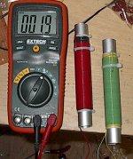
Anyway, they measure about 1.7 ohms in series.
I tried it on the amp running the +/-35V, but it was a no-go, simply not enough current.
It's time for the real power. I'm crossing my fingers.
I was a little low in my measurements, no time to look for a tape measure, I used fathoms - I guess my arms aren't as long as they used to be 😀.
Anyway, they measure about 1.7 ohms in series.
I tried it on the amp running the +/-35V, but it was a no-go, simply not enough current.
It's time for the real power. I'm crossing my fingers.
Attachments
MJL21193
Can you not get hold of wirewound resistors of industrous factories. I found 8 ohm types locally and it would seem to me you will need similar types frequently! connect 4 of 8 ohms for 2 ohms resistors load to test your amp?
Chris
Can you not get hold of wirewound resistors of industrous factories. I found 8 ohm types locally and it would seem to me you will need similar types frequently! connect 4 of 8 ohms for 2 ohms resistors load to test your amp?
Chris
MJL21193
Can you not get hold of wirewound resistors of industrous factories. I found 8 ohm types locally and it would seem to me you will need similar types frequently!
Can you not get hold of wirewound resistors of industrous factories. I found 8 ohm types locally and it would seem to me you will need similar types frequently!
luka said:This is one sick design, from beginning to the end, nice job!!
AndrewT said:I hope you meant slick
Sick or slick, I'll take either as a complement. 🙂
luka said:Hi
You can hope they will heat up a bit, giving you 2R as you need
I thought I'd give them an hour or so for the varnish to completely dry before I use them. My intention is to set them in a metal bowl full of cold water. I just need an idea of how stable the amp is into this low impedance, so these test won't be long.
In the meantime SUCCESS!!! it works on full rail voltage. I didn't trust my CCS arrangement for the VAS, so I changed it to bootstrap (something at least I know). Using my 8 ohm dummy, I have 45.1Vrms at the output before clipping. Running rock steady, no sign of instability at all.
That's 254 watts. Quarter of the way there. 🙂
This figure, proves out my simulations figures for power output, so I should easily hit nearly 900 watts into that ~2 ohm load. The limitation is the power supply, rigged now with only 10,000uF/rail. I'll be doing that test next.
Once you test with the bootstrap+resistors, are you switching back to CCS once it tests well?
My 350W/4ohm amp does fine with bootstrap, but I've wanted to change to CCS because if I clip it real hard, the speaker pulls in for a moment (offset) until the bootstrap cap charges back up. As long as I clip a bit it's OK, just under hard clipping w/speaker I get that.
I'll admit, the bootstrap and resistors is a nice simple way to get good voltage swing.
Twaksak said:MJL21193
Can you not get hold of wirewound resistors of industrous factories. I found 8 ohm types locally and it would seem to me you will need similar types frequently!
Hi,
When I need to do it on Sunday morning, I need to use my ingenuity. 😀
Anyway the ones I made seem to work fine. I just tried it and they didn't blow up

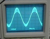
I see some ringing, evident in both halves of the sinewave, but I did hit 34Vrms before clipping. That's about 680 watts. I'm not exactly sure what the resistance is of my load - the POS Extech reads from .2 to .6 with the leads shorted, so it could be as low as 1.5 ohms.
Now, the ringing. There isn't a clear oscillation, just the ringing. More in the top of the wave than the bottom.
Attachments
Doesn't that look like the amp is bursting into oscillation when the voltage goes above or below a certain voltage ? Possibly due to some capacitance across a device varying significantly with voltage ?
Is that oscillation with or without load? What is the output power and load? What is the freqency of the oscillation? It could be global instability due to the output stage slowing down at high currents OR local oscillation in the output stage because of the same thing. If it is local oscillation inserting a resistor between output base buses and drivers could help. Inductor in parallell with resistor is another possibility, Crown uses this in many of their amps.
I suggest you add clamping diodes to the output. It will be nicer to the transistors if clipping into an inductive load. You should also add copper buses for the rails to the output devices. I wouldn't trust the connection to the aluminium from the back of the transistors as aluminum oxidises instantly in air!
I suggest you add clamping diodes to the output. It will be nicer to the transistors if clipping into an inductive load. You should also add copper buses for the rails to the output devices. I wouldn't trust the connection to the aluminium from the back of the transistors as aluminum oxidises instantly in air!
Are you sure that is really oscillation? It could be also power supply ripple. Just slow the time base to 2 - 5 mS / div to make sure.
It can be quite a scary time switching on an amp for the first time.
I tend to get the driver stage working first and apply the feedback to the differential pair from teh driver output instead of the MOSFET output. This way I can check that the driver stage is right first. Only then do I think about connecting the output stage(s).
All my designs already have a microcontroller with a relay to monitor the output for DC so that saves on speakers frying.
EWorkshop1708 said:Once you test with the bootstrap+resistors, are you switching back to CCS once it tests well?
Yes, I'll be going with the schematic posted a few back, the one with the separate active bias on the CCS.
ashok said:Doesn't that look like the amp is bursting into oscillation when the voltage goes above or below a certain voltage ? Possibly due to some capacitance across a device varying significantly with voltage ?
Hi Ashok,
Yes, it seems that way doesn't it. There's no sign of it when the load is 8 ohms (with an even greater voltage swing), so it has to be related to the current output into the lower impedance. Generated in the output stage then back through the feedback?
megajocke said:Is that oscillation with or without load? What is the output power and load? What is the frequency of the oscillation? It could be global instability due to the output stage slowing down at high currents OR local oscillation in the output stage because of the same thing. If it is local oscillation inserting a resistor between output base buses and drivers could help. Inductor in parallel with resistor is another possibility, Crown uses this in many of their amps.
I suggest you add clamping diodes to the output. It will be nicer to the transistors if clipping into an inductive load. You should also add copper buses for the rails to the output devices. I wouldn't trust the connection to the aluminum from the back of the transistors as aluminum oxidises instantly in air!
Hi megajocke,
That picture is the amp operating into a 1.6 ohm dummy load ( i confirmed the resistance - I put it in series with a known resistor).
The rms voltage through that load was 34V, so ~722watts.
It wasn't full blown oscillation, just ringing at the top and bottom portions of the waves.
I have both a Zobel and a Thiele network on the output.
I am trying different things to track down the cause and I'll probably be trying all of your suggestions.
As for the connection to the conductive heatsink, I "lapped" each device in place using a mixture of thermal compound and aluminum filings. I then tested each by driving a 60 watt light bulb connecting between the collector pin and the heatsink. I have much confidence in the electrical connection.
whoandcar said:Are you sure that is really oscillation? It could be also power supply ripple. Just slow the time base to 2 - 5 mS / div to make sure.
Hi,
No, definitely not PS ripple. 🙂
The preceding tests were with the MJE15031 as the VAS driver. I changed to the 2SA1011 to see if there would be an improvement. I also changed the load to my 100 watt/ 4 ohm dummy. It started out ok, and I managed to drive the load to clipping (~43Vrms - 462 watts), but then it started to go crazy. bottom half of the wave dissolved into ringing and then she flatlined. That 1011 is toasted. I'm not sure why it konked, I didn't let it clip for long, half a second maybe.
So, I changed back to the MJE and tried it again. Looks fine at 4 ohms with the MJE as VAS. My 4 ohm dummy can't take ~500 watts for long, so I shut it down.
I found 2 10 watt, 1 ohm resistors in my junk heap and paralleled those and added them in series to the homemade "resistors" to bump up the impedance to 2 ohms. I also added a silver mica 100pF to the B-C of the lower driver (like in the P68). I hook it all up and it occurs to me that maybe my homemade resistors are inductive, even though I wound those bifilar. Could this be the reason I am see this ringing?
Anyhow, I try it again and the ringing is all but gone in the lower part of the wave and greatly reduced in the top half, so the cap across the driver is doing something.
I get about 5 seconds at full power before one on the 10W resister pops, then the other goes too. I didn't put these in the water with the others, it being regular tap water, I didn't want to submerge the bare wires.
I wouldn't call that ringing, ringing is to me something that happens around "sharp" edges. For example when clipping or doing square-wave tests. It is very possible for circuits to oscillate only at certain output currents due to the fT varying with Ic.
You could try scoping the VAS output node, the output bases and the output before output inductor//resistor to see where it originates from. If the oscillation is stronger on the output of one stage than it's input you have a local oscillation.
You could try scoping the VAS output node, the output bases and the output before output inductor//resistor to see where it originates from. If the oscillation is stronger on the output of one stage than it's input you have a local oscillation.
megajocke said:I wouldn't call that ringing, ringing is to me something that happens around "sharp" edges. For example when clipping or doing square-wave tests. It is very possible for circuits to oscillate only at certain output currents due to the fT varying with Ic.
You could try scoping the VAS output node, the output bases and the output before output inductor//resistor to see where it originates from. If the oscillation is stronger on the output of one stage than it's input you have a local oscillation.
I had similar problems and it was the VAS in the end.
I just upped the cap from b to c to 220pf.
megajocke said:That would work if global oscillation is the problem. 🙂
I wasnt getting full oscilation on my amp just certain parts of the waveform.
Its worth a try to see if it dampens out the osc without losing too much bandwidth.
Global oscillation doesn't have to mean it oscillates all the time, I meant global as in loop oscillation VS local oscillation. I'd start with measuring if it is global oscillation or not, but changing the cap is of course another way to test it.
It helps keep the CFP under control, Try the cap on both drivers, top and bottom, and then try a larger cap value, like 220pf or more. The output stage has more current than a VAS, the smaller cap values don't make as much difference with output stage.
Have you tried the larger zobel cap yet? 0.22 or 0.47uf?
Have you tried the larger zobel cap yet? 0.22 or 0.47uf?
- Status
- Not open for further replies.
- Home
- Amplifiers
- Solid State
- 1000 Watt Sub Amp: Design / Build