MJL21193 said:
Would increasing the Miller cap defeat the purpose of the low Cob VAS?
Hi John,
Something to keep in mind is that understanding and designing for stability is not a simple matter.
As Glen has already mentioned, the faster VAS probably needs more Cdom to provide the same stability as the large MJ device. No the MJ is not better, what it has is a large internal Cdom that allows us not to have to put a large one in the design but obviously it is a false "improvement" since the internal Cdom is highly non-linear and is a source of distortion. What is important is the dominant pole position, the advantage of the faster VAS is that the smaller non-linear internal C is swamped by the larger (linear) external Cdom when the pole position is held constant. You might have to add 200 to 500 pF to get the same pole position. You could look at the open loop -3dB point to test this.
I do like the CFP driver and have had one with a twist in mind for my next design for some time now. However, stability under real world conditions has to be kept in mind and investigated.
You question why making the VAS faster makes the stability worse. The pole formed by the Cdom cap and the diff amp output impedance is intended to be the main low freq pole of the design when Cdom is the compensation scheme. Other poles must be much higher in freq, and using a "better" VAS makes it worse since your moving up the dominant pole freq when you do not compensate externally to bring it back down.
There is the issue of output stage bandwidth with the increased capacitance with so many output devices. However, things do scale, there is more capacitance but if you scale up the drive to the output stage then the bandwidth stays the same. You have a large MJ device driving the output devices on, and you have a very small 3.3 ohm resistor to turn them off. This is good. But remember you are using slower devices than in your Patchwork amp. Also, that particular MJ driver is slow, might try a faster high power type. I notice that you have no stoppers in the output stage, don't know if they might help.
OK, so the amp has problems in clipping, this is not surprising, BJTs are *very* slow coming out of saturation so the output stage pole is lowered when you clip, and margin is lost. I believe that an HF oscillation starts when you clip and this causes the DC offset.
I suggest using the better VAS but keep in mind that it has to be large enough to handle the worst case overload and capacitive drive conditions. The higher rails in this design indicates that you should keep a closer eye on SOA for the VAS.
Another thing to keep in mind is that high open loop gain reduces distortion when operating in the linear region below clipping. However, once the output stage clips the high gain means that the earlier stages will be driven harder as they attempt to correct for the output distortion. You need to consider saturation of the earlier stages so that they recover gracefully. Reducing the OL gain as you have, obviously is one solution.
You might consider a single resistor in place of R9 and R20, 10-15 ohms.
Here's a big amp that I did as a young teen; that is a Hafler 500 on top of it as an indication of the size. I'm thinking of rebuilding it into mono blocks some day since it needs to be recapped:
http://members.aol.com/basconsultants/big_amp.jpg
Pete B.
AndrewT said:Hi,
i think the capacitance of the VAS changes as Vce changes.
A low capacitance transistor//ideal cap is better than a high capacitance transistor.
I would go further and remove the 1011 which is a driver type and substitute a true low capacitance transistor for the VAS. Then EF it to generate the current required for the next stage.
Hi Andrew,
As mentioned earlier, I have some low Cob, high voltage devices lined up: 2SA0914 and it's NPN complementary. I will be using this one for the VAS. I have some concerns about dissipation though. These are not high power devices.
EWorkshop1708 said:Project Stability!!!
With all our help here, we can help get this man's amp stable! 🙂 😱 😀
Rod's design in BOTH P3A and P68 use a 100pf cap on the b-e junction of the drivers. Your amp has no such compensation. I did this myself but used 1000pf (102) and it worked fine, even plays great with treble under testing. You may want to try this to improve stability.
Hi EWorkshop,
Here is the current state of affairs:
- Amp runs stable now since the removal of he EF on the VAS.
- When using the 2SA1011 for the VAS, 10-20VDC shows at the output when the input cable is unplugged. This doesn't happen when I use the MJE15031 for VAS.
I am still operating on +/-35v supply due to concerns about the DC at the output. I will increase it to full supply voltage today and check to see if the clipping performance has improved, but I'd really like some ideas as to where this DC is coming from and why it doesn't happen with the other VAS driver.
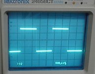
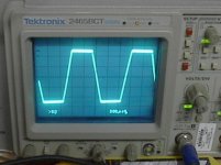
I did notice the compensation cap Rod added to the lower driver. I assume that clears up the minor ringing evident in the negative going part of the wave when using the MJE as the VAS.
Here's a pic of the amp running with a ~1kHz squarewave. This is with the MJE15031 as VAS driver.
Attachments
Also:
You might consider a single resistor in place of R9 and R20, 10-15 ohms.
Isolating your two current sources is important as has been already mentioned. I believe Self provides an explanation.
I also suggest diff pair degeneration as long as you maintain enough open loop gain.
Some small resistance in the emitter leads of Q3 and Q25 will limit the maximum current driven into the base of the ouput devices and how deeply they're driven into saturation. Something around 10 ohms keeping in mind that it will limit your max output current drive and don't go too large.
Is the 10-20V offset positive or negative?
Have you tried driving that square wave into clipping? Probably not a safe thing to do at the full supply voltage but not a problem at +/- 35V.
Pete B.
PB2 said:Also:
You might consider a single resistor in place of R9 and R20, 10-15 ohms.
Glad to see you here Pete,
Even though it matches what Rod Elliot did in the P68, I investigated this in the simulation and deliberately kept that low value and connection to the output bus to allow these to share some output current.
PB2 said:
Isolating your two current sources is important as has been already mentioned. I believe Self provides an explanation.
I also suggest diff pair degeneration as long as you maintain enough open loop gain.
Some small resistance in the emitter leads of Q3 and Q25 will limit the maximum current driven into the base of the output devices and how deeply they're driven into saturation. Something around 10 ohms keeping in mind that it will limit your max output current drive and don't go too large.
Is the 10-20V offset positive or negative?
Have you tried driving that square wave into clipping? Probably not a safe thing to do at the full supply voltage but not a problem at +/- 35V.
Pete B.
The DC is negative. It extinguishes the LED, similar to the clipping behavior.
I have clipped the squarewave, and with the MJE it clipped cleanly. With the 1011, It completely collapses to the 20VDC output. This is interesting, because I switched back to the MJE VAS and it's now behaving the same way - clipping collapses to DC output. Is this a clue that something maybe damaged?
Ok, let's break it down. At this time I'm willing to change anything in the amps front end within the design criteria: this is a subwoofer amp, and will not operate above~100Hz, therefore we should forgo any improvements that don't deal with stability, distortion (within limits) and clipping.
Lets look at the input first. I have the basic LTP with a MPSA42 as the current source. I was tempted to use just a resistor here, but thought this better. Wg_ski suggests lower values for R1 and R2. Pete says degeneration emitter resistors for Q12,Q13. The current mirror is gone for good.
Other possible concerns?
Attachments
MJL21193 said:
Glad to see you here Pete,
Even though it matches what Rod Elliot did in the P68, I investigated this in the simulation and deliberately kept that low value and connection to the output bus to allow these to share some output current.
The DC is negative. It extinguishes the LED, similar to the clipping behavior.
I have clipped the squarewave, and with the MJE it clipped cleanly. With the 1011, It completely collapses to the 20VDC output. This is interesting, because I switched back to the MJE VAS and it's now behaving the same way - clipping collapses to DC output. Is this a clue that something maybe damaged?
Ok, let's break it down. At this time I'm willing to change anything in the amps front end within the design criteria: this is a subwoofer amp, and will not operate above~100Hz, therefore we should forgo any improvements that don't deal with stability, distortion (within limits) and clipping.
Lets look at the input first. I have the basic LTP with a MPSA42 as the current source. I was tempted to use just a resistor here, but thought this better. Wg_ski suggests lower values for R1 and R2. Pete says degeneration emitter resistors for Q12,Q13. The current mirror is gone for good.
Other possible concerns?
Yes it seems that something is broken, or perhaps you have a short somewhere.
LED going out, probe around and find out why, check supply rails, transistor voltages, something is seriously wrong. Do you have the LED biased on strongly enough? Don't like that 10 ohm resistor in the front end ground. Are all the resistor values correct as installed, etc.
I think it is important to understand the difference in the VAS, I'd like to see you get it working normally with the slow part, then see if it matches with the faster part and say 1000 pF as a Cdom cap. This is just a test to rule out global loop oscillations, and help determine if it is local to the output stage. However, with 20V DC offset something is seriously wrong in the global loop.
Degeneration resistors are very basic to improving the overload characteristics of the front end. See the long discussions related to the Leach design. I suggest that you look at the VAS collector during clipping and you might be surprised with the behavior. I have a strong preference for a mirror in the front end, even if you need a bigger Cdom cap to reduce HF gain, it helps keep the front end balanced.
Basically, I prefer the mirror, and EF on the VAS, with a larger Cdom cap to make it stable. The theory suggests that even if you use methods to increase the OL gain reducing it again with a Cdom cap should provide the same stability. You have a slower output stage than with your other amp, so stability will be more difficult.
I know that you're going to do what works best for you and gets you to a solution fastest so I won't go into a lot of detail on the rest.
Pete B.
MJL21193 said:
Ok, let's break it down. At this time I'm willing to change anything in the amps front end within the design criteria: this is a subwoofer amp, and will not operate above~100Hz, therefore we should forgo any improvements that don't deal with stability, distortion (within limits) and clipping.
Other possible concerns?
I am with you 100% Were not concerned with high speeds, we want bass, not super fast transistors and HF capability. IMO it won't hurt to filter down this amp a little bit. CFP output is prone to oscillation, so it needs a little help, but will sound great.
I'm not sure why you are having problems clipping. IMO the stability has something to do with it. CFP usually clips strong and hard, and I prefer it to EF for subs for strong output.
Try this...
You could try 100pf at b-e of Q14 current source
A 1 or 2.2 or 3.3 ohm resistor for base of drivers Q3 and Q25 I would try 1 ohm first.
Try 1000pf (102) on the B-C of either your predrivers or drivers, or maybe a smaller value on both. Being you have 33ohm on base, a cap on that transistor combined with the base resistor, would filter out some HF or RF. I used 100 ohm base and 1000pf and no problems.
Use emitter resistor of 2.2-10 ohms on CFP drivers (Q2,Q16). I used 4.7 ohms on my driver emitter, this stability tip was given to me on someone here at diyaudio about 2 yrs ago. Sorry I forgot to mention it earlier.
PB2 said:
Yes it seems that something is broken, or perhaps you have a short somewhere.
LED going out, probe around and find out why, check supply rails, transistor voltages, something is seriously wrong. Do you have the LED biased on strongly enough?
I know that you're going to do what works best for you and gets you to a solution fastest so I won't go into a lot of detail on the rest.
Pete B.
Hi Pete,
I changed R39 to 220 ohms and that solved the DC/clipping collapse problem. I guess the VAS is drawing too much current at ~11mA with this setup. Perhaps we need to look at a separate active bias for the VAS CCS.
Changing R39 reduces VAS current to ~5.5mA. This raises a question: how hot should the VAS run? I know from the Patchwork project, lowering the VAS current to ~5mA helped on many fronts, and didn't hurt performance in the least. Full power distortion testing with Anatech on that amp showed remarkable performance, as accurately predicted by the simulator.
Stick around and explain this stuff to my Pete, I'm not really in any hurry here to finish this. It's as much for the learning as the end result that I'm doing this.
EWorkshop1708 said:
I am with you 100% Were not concerned with high speeds, we want bass, not super fast transistors and HF capability. IMO it won't hurt to filter down this amp a little bit. CFP output is prone to oscillation, so it needs a little help, but will sound great.
Hi EWorkshop,
I seem to have stability in check, at least for now, so I'll hold off on any changes to the OS until we get the front end sorted out. Sometimes, I'm tempted to just buy a wack of LME49810's and use those, rather than trouble myself with the complexities of dealing with a foolproof front end.
I guess that's where the fun is though. 🙂
I have played with the simulation for a bit and come up with the following schematic update.
I tried to find models for the new transistors I'll be using , but was unsuccessful. I did find models in that closely match these, especially the capacitance. I used the ZTX458 model for the 2SC1953 and the ZTX558 for the 2SA0914.
I have made some of the recommended changes. The schematic only has 2 pairs of outputs showing, but that's just so I can fit the drawing in the space here.
The original values for R1 and R2 in the P68 seem to be correct. At 560 ohms the currents through the differential pair are balanced, at least in the simulation.
According to the sim, accounting for all of the losses, I can realistically expect ~400 watts into 4 ohms from this with the power supply I have. Power into 2 ohms would be ~640 watts.
It would need +/-90 volt rails to achieve the full 1000 watts.
I tried to find models for the new transistors I'll be using , but was unsuccessful. I did find models in that closely match these, especially the capacitance. I used the ZTX458 model for the 2SC1953 and the ZTX558 for the 2SA0914.
I have made some of the recommended changes. The schematic only has 2 pairs of outputs showing, but that's just so I can fit the drawing in the space here.
wg_ski said:Removing the current mirror in the front end helps some by reducing open loop gain - but make sure you trim the load resistor to balance the current in the LTP. It will *work* with a wide range of values, but if you want to keep distortion down use the one that keeps the diff pair currents the same.
The original values for R1 and R2 in the P68 seem to be correct. At 560 ohms the currents through the differential pair are balanced, at least in the simulation.
According to the sim, accounting for all of the losses, I can realistically expect ~400 watts into 4 ohms from this with the power supply I have. Power into 2 ohms would be ~640 watts.
It would need +/-90 volt rails to achieve the full 1000 watts.
Attachments
MJL21193:
Sometimes, I'm tempted to just buy a wack of LME49810's and use those, rather than trouble myself with the complexities of dealing with a foolproof front end.
Hi John,
I agree completely with your tempting thoughts. If there's no need to have a high-end amp to drive full range complex speakers, there is an easy way to build problem free amp, especially for subwoofer applications.
LME49810 front-end in ProJet Power Module works fine in few instalations and its best feature is low frequency control of the output devices 2SA1987/2SC5359 (very low output resistance of the module). Output power is very flexible regarding +/-100Vmax of the LME supply limitations.
An externally hosted image should be here but it was not working when we last tested it.
I wanted to suggest this, but since you already separated the VAS CCS from the frontend one...
Mr. Pass suggested (maybe it was the A40?) to use a resistor in the base of the VAS CCS if this transistor was driven from the same voltage source as the frontend one: so when the VAS clips, it won't make the voltage source collapse thus latching up the whole feedback scheme.
Could I suggest a protection transistor for the VAS? Sensing the current in R3, removing the drive to the 2SA914 when the current goes more than 3-4x the quiescent current in the VAS.
Has already been suggested to unite R11 and R21 in one resistor and parallel it with a capacitor? R30 should be useless.
I admire your chassis with envy 😎
Lazy Cat said:
Hi John,
I agree completely with your tempting thoughts. If there's no need to have a high-end amp to drive full range complex speakers, there is an easy way to build problem free amp, especially for subwoofer applications.
LME49810 front-end in ProJet Power Module works fine in few instalations and its best feature is low frequency control of the output devices 2SA1987/2SC5359 (very low output resistance of the module). Output power is very flexible regarding +/-100Vmax of the LME supply limitations.
Hi Lazy Cat,
Your Projet modules are very good looking,

One thing that keeps me from taking the easier route, using the LME, is that I find that doing things with discrete components is educational. The more I play with this, the more I learn.
Giaime said:
Could I suggest a protection transistor for the VAS? Sensing the current in R3, removing the drive to the 2SA914 when the current goes more than 3-4x the quiescent current in the VAS.
Has already been suggested to unite R11 and R21 in one resistor and parallel it with a capacitor? R30 should be useless.
I admire your chassis with envy 😎
Hi Giaime,
I will look into the VAS protection. We went through that on the Patchwork, but it introduced too much distortion there. In this case, I'm not worried about the addition of a little distortion, so I'll include it.
I don't want to separate the CFP's from the output. As it is, they share some of the output current. true, R30 is probably not needed.
Thanks, the chassis is on hold until I get much of the electronics taken care of. Just to show off to anyone who hasn't seen it yet, here it is again, at least most of it.
Attachments
MJL21193 said:
Hi Giaime,
I will look into the VAS protection. We went through that on the Patchwork, but it introduced too much distortion there.
Working with the simulation, I realized the conclusion we (I mean Glen - G.Kleinschmidt) came too: the VAS doesn't need protection. In Glens words: "Current limiting of the VAS is only generally needed if the output stage is also current limited with a clamping circuit (which typically diverts the VAS current to the load). In the basic unprotected “D.Self” topology such as yours, it really isn’t necessary.
Q4 will saturate of when the output voltage rails out in the positive direction, but the Q6 will still only draw from the VAS the small base current it needs to maintain the peak output current through the load.".
I drove the real amp well into clipping, and it looks good. I left it like this long enough to take 3 pictures, (pick which is the clearest) about 30-40 seconds. The VAS didn't get hot at all. The amp is only running on half the supply voltage, but the simulation give the same results at full power.
Attachments
MJL21193 said:
According to the sim, accounting for all of the losses, I can realistically expect ~400 watts into 4 ohms from this with the power supply I have. Power into 2 ohms would be ~640 watts.
It would need +/-90 volt rails to achieve the full 1000 watts.
A blunder on my part - I ran the sim with just the 2 pairs of outputs. I was off on the power estimates.
Correct figures would be easily 480+ watts into 4 ohm load, and the real limit on the 2 ohm power being the VA rating of the transformer I have (850VA), so enough voltage for ~900 watts into a 2 ohm load before clipping.
Distortion is ~0.04% at full power.
Tomorrow morning, I will try it with the full power supply to see how it runs in the present configuration. The problem I have is load testing it. My dummy load is a maximum 100 watts/8 ohms.
What can I use for a 2 ohm, 1kW dummy load? A roll of Romex house wire?
That would be 250 meters of #14 wire to equal 2 ohms resistance. Or 818 feet. A roll has 250', the wire is 2 conductor plus a ground so using all three I'd have 750' - close enough. 🙂
four dummy loads of 100W 8r0.MJL21193 said:My dummy load is a maximum 100 watts/8 ohms.
What can I use for a 2 ohm, 1kW dummy load? A roll of Romex house wire?
EWorkshop1708 said:The heat elements of a blow-dryer or toaster will also work.
Aha! Hadn't though of that. The next time I'm at Goodwill I'll pick up a toaster or two. What I have on site now is a big, expensive, glow-in-the dark, motorized transport, assimilated by the Borg, bought by wife #2, stainless steel behemoth. Risk death, if I were to touch that.
It does make some damn fine toast though...🙂
AndrewT said:four dummy loads of 100W 8r0.
Hey Andrew,
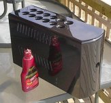
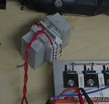
I only have one (see pic below), which I custom built thinking it would be enough for most of the stuff I do. I don't have the resistors to build 3 more. I don't want to use up 3 more of my PIII cooler heatsinks either. SO...
I am making two 1 ohm resistors - 24 gauge telephone wire (insulated) bifilar wound in two layers around a 3/4" aluminum tube. I will put them in a cooling liquid. This is a more permanent solution, and cheap as I have the wire and tubing layer around.
Attachments
- Status
- Not open for further replies.
- Home
- Amplifiers
- Solid State
- 1000 Watt Sub Amp: Design / Build