I'm definitely not the expert on this, but wouldn't that configuration couple any power supply ripple you may have through to the base of your transistor, making it audible?
Like I said, I am sure I am missing something here. . . .
EDIT, or I guess you can make sure to have small enough caps where that wouldn't happen. . . Hmm. . . I'm still working with this one. . .
Like I said, I am sure I am missing something here. . . .
EDIT, or I guess you can make sure to have small enough caps where that wouldn't happen. . . Hmm. . . I'm still working with this one. . .
dfdye said:I'm definitely not the expert on this, but wouldn't that configuration couple any power supply ripple you may have through to the base of your transistor, making it audible?
Like I said, I am sure I am missing something here. . . .
EDIT, or I guess you can make sure to have small enough caps where that wouldn't happen. . . Hmm. . . I'm still working with this one. . .
Hi,
These caps will only be used if necessary. I'm hoping they won't be needed.
Rod Elliot used these in at least 2 of his amps: the P3A and the P68.
BTW, I've got 41,000uF of smoothing per rail. I have no idea how much ripple is left.
dfdye said:I'm definitely not the expert on this, but wouldn't that configuration couple any power supply ripple you may have through to the base of your transistor, making it audible?
Like I said, I am sure I am missing something here. . . .
EDIT, or I guess you can make sure to have small enough caps where that wouldn't happen. . . Hmm. . . I'm still working with this one. . .
I think it shouldn't be audible, it's value is too small. Internal transistor parasitic capacitances are several times bigger than 100pF.
Cheers
To be honest with the high power dummy load thing...
if you need to use it for any extended amount of time at ~750 RMS
you will need some serious heatsinking/cooling it would be better to use a suitably rated power resistor.
at work generally we use resistors which are approx 2.5 mm (OD) nichrome wound on a ceramic former, you can wind half one clock wise and half anti to reduce inductance.
Having said that, 36 x 10W power resistors in parallel will *probably* not pop if you use the method AndrewT described here:
http://www.diyaudio.com/forums/showthread.php?s=&threadid=53264&perpage=25&highlight=&pagenumber=18
Dubbed the "-20dB flick switch method"
I used it to test ~500RMS 8R with no dramas...
hope this helps good luck with the next phase of your build !!!
-Dan
blueskynis said:
I think it shouldn't be audible, it's value is too small. Internal transistor parasitic capacitances are several times bigger than 100pF.
500pF for the MJL's.
danieljw said:To be honest with the high power dummy load thing...
if you need to use it for any extended amount of time at ~750 RMS
you will need some serious heatsinking/cooling it would be better to use a suitably rated power resistor.
at work generally we use resistors which are approx 2.5 mm (OD) nichrome wound on a ceramic former, you can wind half one clock wise and half anti to reduce inductance.
Dubbed the "-20dB flick switch method"
I used it to test ~500RMS 8R with no dramas...
hope this helps good luck with the next phase of your build !!!
-Dan
Holy smoke! 500 @ 8 ohms? That's 100V rails!?
Yes, Andrew mentioned that method to me before.
The testing I want to do will be relatively short duration. I would be submerging the load in cold water for cooling. This is what I did for my homemade "resistors", and the water got fairly warm after a brief test.
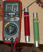
Mainly, I'd like to know if the power on these resistors is derated, similar to a transistor, or will are they good for ten watts regardless of temperature (within reason, of course).
I could just make another wound resistor of say ~.5 ohm and put this in series with the other two. Pic below for those new, that don't know about my resistors.
Attachments
yes 100V rails is good for making smoke from things.... speakers/mosfets/resistors etc 🙂
maybe if you wind another one and flip it so the winding goes in the opposite direction to the other it will cancel some of the inductance.
-Dan
maybe if you wind another one and flip it so the winding goes in the opposite direction to the other it will cancel some of the inductance.
-Dan
Fair enough. I'm just being paranoid. Plus, the ripple wouldn't be getting amplified, so even if it did get coupled, the amplitude would be quite small as was pointed out (41,000uF = 🙂 ).blueskynis said:I think it shouldn't be audible, it's value is too small. Internal transistor parasitic capacitances are several times bigger than 100pF.
Cheers
I'm good now. Had to get my head out of the dark place, so to speak.
danieljw said:yes 100V rails is good for making smoke from things.... speakers/mosfets/resistors etc 🙂
maybe if you wind another one and flip it so the winding goes in the opposite direction to the other it will cancel some of the inductance.
-Dan
Hi Dan,
The ones in the picture are bifilar wound to kill inductance, I will just make another one, with an impedance of ~.5 ohms to make it to 2 ohms. My idea is to see how it performs at this low impedance. My last attempt was stable at 4 but unstable at what I now know to be 1.5 ohms.
These next tests will be run on the full complete power supply, not like before with only 10,000uF/rail. That may make a difference too.
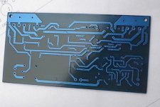
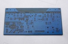
I spent most of last night doing another board layout. This really needs to be the final one now. Three times doing the same layout is a killer.
The board is bigger to accommodate the MJL4281A/4302A driver pair. I have tried to include all of the compensation components recommended, some of these will not be used unless needed. Better to allow the space on the board for them though, then try to squeeze them in later. I dislike a messy PCB.
As originally planned, I have also included the Linkwitz transform circuit on this board and, like on the last one, the relay that pulls the input to ground when the amp is off. My old version of this could produce a very heavy thump when powered up or down.
Board has been etched, silkscreened and is now getting the soldermask (I really need to keep this one).
Attachments
I have stalled out a bit. I started to stuff the new board other day, got half done and stopped. Took a break to go do something else, and haven't gone back to it. Most of the amp section components are in, with just the LT components left to do.
Hard to maintain motivation on big projects like this. There's a certain amount of pressure to get it done also if you are posting the progress on here. Of course, this is self imposed.
I'll be getting back to it on the weekend, so I expect to have an idea of it's performance by then. Hopefully everything works out and I can start to button this one up.
i hear you,
then again you dont want to rush it and mess it up !!!
but we want to see the results
- no pressure !
🙂
-Dan
then again you dont want to rush it and mess it up !!!
but we want to see the results
- no pressure !
🙂
-Dan
danieljw said:i hear you,
then again you dont want to rush it and mess it up !!!
but we want to see the results
- no pressure !
Hi Dan,
No rush. I want this to be as complete as possible before I use it. In the past I have pushed things into service before they were done and regretted it, as it takes a force of will to take them out of active duty to the shop to be finished.
There is some pressure. Just about every week a thread shows up for a monstrously powerful amp, usually from the newer members. Normally, these threads don't amount to much. In my limited attendance here, I haven't seen one that was actually built and operating. I don't want this to be viewed as a pipe dream. I always finish what I start, for better or worse. 🙂
One of my problems, and the reason I stalled before is the fear that the beautiful board that I so lovingly laid out and etched will have a fatal flaw that will undo all of the hard work. This is, for me, a mental hurdle to overcome.
I almost always make some mistake, but I am improving in my troubleshooting skills. I always manage to find the source of the problem, so I guess it works out in the end.
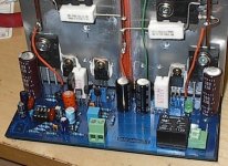
Another look at the new amp board, this time the component side. I have found the time since my last post to finish populating this and I'll talk about that next.
Attachments
MJL21193 said:
In my limited attendance here, I haven't seen one that was actually built and operating. I don't want this to be viewed as a pipe dream. I always finish what I start, for better or worse. 🙂
I have finished 2 amps while being a member on this board.
One was 600 watts RMS and the other 275 watts RMS.
The current project is a MOSFET 1000W RMS power amp.
nigelwright7557 said:
I have finished 2 amps while being a member on this board.
One was 600 watts RMS and the other 275 watts RMS.
The current project is a MOSFET 1000W RMS power amp.
Hi Nigel,
Yes, I know these things are being built, but there have been none documented here, at least not lately. Add to the the general amusement and scorn the veterans show these threads.
Fact of the matter is: I need this amp. I can't run my sub without it. For the huge transients that will happen with a Linkwitz transform, it is wise to have more power than you need so that It will not clip.
Anyhow, new amp board for the frontend is up and running. Last night I finished putting the components in and earlier this evening, I tried it at +/-35VDC. Naturally, I had the VAS wrong again. This time, it was from the layout. The pin out for the footprint was wrong - CBE instead of (for the 2SA914) ECB. I had to flip it and cross the collector lead over the base lead (like crossed fingers). It looks like it is walking away. 🙂
That done and everything looks A-OK. I am in the process of hooking up the permanent PS to give it a try.
Here's how it looks all dressed up:
Attachments
MJL21193 said:Hi Nigel,
Yes, I know these things are being built, but there have been none documented here, at least not lately. Add to the the general amusement and scorn the veterans show these threads.
I am pleased to hear things are going well.
I built a MOSFET amp with a +/- 45 volt supply and found that it wasnt dealing with transients very well. The transients just got clipped ! The MOSFETs need at least 2-3 volts to switch them on so that has to be subtracted from the voltage rail to get max voltage out.
My next amp uses a power rail closer to 60 volts and so has a bit more head room.
Alright. Full power test went well. No mishaps when I connected the supply. All voltages look good, VAS is not getting too hot, no sign of oscillation. Measured DC offset is less than 10mV, so very good indeed. I was a little concerned with this, as I had a rather high offset in the last try (~80mV).
Connected the 8 ohm load. Drove that to clipping. No sign of instability. Clipping starts at 45.2Vrms output so that's a little more than 250 watts. Clipping is nice, uniform. Switch to a squarewave and that looks clean. Flat with no ringing, even when driven to clipping.
I haven't found time to wind another "resistor" so I just used the two I had made. These presents a 1.5 ohm load for the amp. This is where the trouble showed up last time, with heavy oscillation at the top and bottom of the wave. Very pleased to say that the amp handled this load perfectly. No instability at all. Driven to it's maximum, 36.6Vrms output before clipping, this is over 890watts output into this load. Briefly driven into clipping still looks good, very uniform without any bad behavior.
I have one slight problem though, not enough quiescent current, so my Vbe multiplier is not quite right (could be a bad pot).
I have to thank those that gave me all the good advice. I'll be posting the schematic with the present configuration, to show the compensation parts in place now. As it turned out, I didn't need much.
I'll post some pics soon.
That's great!!! 😀
I'm glad it's now working and on its way to becoming a finished project.
I was wondering if your old supply couldn't take the low ohm loads well.......but I see you are now using more power than before.
Glad you finally got rid of the oscillation. 😀
*If you are having trouble with the bias adjustment, try different ranges of fixed resistors + the POT until you get it right. When I built my sub amp, I tried several resistors, until I got it right by using a 1K ohm resistor + a 5K ohm POT. Now my stage is different than yours, but I feel it applies. I notice the lower fixed resistor also makes the bias adjustment much less sensitive when turning the POT, so it's easier to set the bias current.
EWorkshop1708 said:That's great!!! 😀
*If you are having trouble with the bias adjustment, try different ranges of fixed resistors + the POT
Thanks EW,
The bias adjust has a 3.6K resistor above the pot (1K) and a 1K below. I changed the 1K to 500R and now it's fine. Right now I have it set for ~25mA through each device at idle. I'll leave it running tomorrow for a while to see how well it maintains that once it's warmed up.
Yes, before the power supply wires to the amp were tiny - 22 gauge and pretty long so I was losing some there.
I am very pleased with what I'm seeing, especially the power output. Rock solid stability into the 1.5 ohm load is more than I expected.
I have just finished a heatsink for the VAS, as I see this does get warm. It being a 50mA device, I don't want to take the chance on overheating it.
Next up is to get the on board Linkwitz transform working. It provides 18db of gain at 20Hz to make those big drivers pump.
Hopefully, I haven't botched anything there.
I'll need to hook up the +/-15V power supply to give it a try.
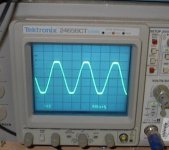
Here is a pic of the clipping performance into the 1.5 ohm load. A little blurry, but this was the best out of 4 that I took. This is almost 900 watts into my homemade resistors. The leads from these (which are just the tail ends of the 24 AWG telephone wire) start to smoke after a few seconds.
The resistors themselves are in a bowl of water.
The resistors themselves are in a bowl of water.
Attachments
- Status
- Not open for further replies.
- Home
- Amplifiers
- Solid State
- 1000 Watt Sub Amp: Design / Build