EWorkshop1708 said:I'll second this. Easy way to get the voltage you need from the toroid.
About the secondary power................
Now I used the Radioshack 2A 12.6V-0-12.6V myself for my amp project, and used it both for the relays and preamp, and it was ok.
Are you getting pops and clicks when using the relays?
TBH, I'm not even sure that the power supply is the problem. Output from the LT is Krap now though, so just putting 2 and 2 together. I really need to try it on a separate supply to make certain.
doesn't seem reasonable that it's something else - it was working fine before.
On a brighter note, I have finished polishing the case, and it's looking quite spectacular. My camera will not do it justice, so I won't bother taking a pic. Suffice to say that it's the best I've done so far.
MJL21193 said:
TBH, I'm not even sure that the power supply is the problem. Output from the LT is Krap now though, so just putting 2 and 2 together. I really need to try it on a separate supply to make certain.
doesn't seem reasonable that it's something else - it was working fine before.
Well...it certainly took a while to find the problem.
I constructed another +/-15V supply to test the LT and found the output was still no good - very distorted. Searched and searched for what could be the possible cause. Solder bridge? No. Loose component? No. Bad opamp? No.
I did some measurements with the power on and hooked up the oscope to look at different places. With the scope, I saw part of the output on the supply! Also on the signal ground. Studied the board, trying to figure out how this could be. Shut the power off and checked the resistance between the signal ground and the main ground - 22K!! This was supposed to be 10 ohms, that would be the value of R42. Look at R42, it looks like a 10 ohm, the bands are correct. Pull it out and measure it - 22K.
Now, that was 10 ohms when I put it in, because I measured it (I measure every resistor). How is it that it changed? The amp won't work properly with this value and it was working fine before.
The resistors used here are ultra cheap ones from Sure Electronics (Ebay). Maybe they weren't such a good deal after all.
Anyway, replaced it wit a known good one from Digikey and everything works A-OK now. I will be giving it a test drive on the sub shortly.
Can be so difficult to troubleshoot something like this! I've seen resistors change value permanently from severe overload, but it doesn't sound like that is something that could have happened here (it would likely be discoloured anyhow in this case). Might just be a very poor quality one like you say. Look forward to your results testing it with the sub 😀 😎
Dr.EM said:Can be so difficult to troubleshoot something like this! I've seen resistors change value permanently from severe overload, but it doesn't sound like that is something that could have happened here (it would likely be discoloured anyhow in this case). Might just be a very poor quality one like you say. Look forward to your results testing it with the sub 😀 😎
This resistor is for isolation for the signal ground, so it didn't see any excessive current. It's a bit worrisome - I've built quite a few circuits with these resistors. Now I'm wondering what will happen next.
It's connected and operating trouble free. I'm putting it trough it's paces right now..

One thing is that this amp has more gain than the Rod Elliot P68, so I had to readjust the level on my HTR. A tad too high. 🙂
Also, I think I need to make an active filter to cut below 20Hz. The LT tries to boost this too much and given the LFE content in some movies, I think it would be a wise move. I just tried "Cloverfield" and there is too much. Those big 18" cones pumping in and out at 8-10Hz is not healthy.
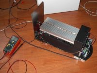
Here it sits on the floor, halfway to the woofer. I have installed the back panel - a piece of stainless steel. Mounted the banana jacks and even cut in the IEC connector. There is still a lot of work left to do before it's complete and in it's case.
Attachments
MJL21193 said:
This resistor is for isolation for the signal ground, so it didn't see any excessive current. It's a bit worrisome - I've built quite a few circuits with these resistors. Now I'm wondering what will happen next.
I had an amp not work too and when i looked into it one of my MPSA42's had gone faulty and had a gain of 1 !
Of course when i took them out one by one to test them it was the last but 1 that was faulty ! Sods law I suupose.
I had an intriguing fault another time where the amp output would start off correct and slowly go negative until it reached the negative rail. In the end it was the input resistor had a dry joint allowing the input to float around.
Is there a high current path between the two sides somewhere? Film resistors aren't very pulse proof. Could it have been zapped when connecting to other equipment?
nigelwright7557 said:
Of course when i took them out one by one to test them it was the last but 1 that was faulty ! Sods law I suupose.
That's usually the way it works for me too. I get discouraged and want to strip the whole board and start again, rather than try to find a needle in a haystack...
Luckily, I keep my head. 🙂
megajocke said:Is there a high current path between the two sides somewhere? Film resistors aren't very pulse proof. Could it have been zapped when connecting to other equipment?
All connections to equipment were made while the power was off.
The resistor changed at some point between my last test of the LT and the next time, when I had finished wiring everything and put it all together. That was my reasoning for suspecting the low voltage power supply.
I don't know. I have about 2000 of these resistors, in all values and now I can't trust them. Still, not much of a loss if I were to dump them - they only cost $10.00 or so. Not worth the aggravation to find if another one goes faulty.
I listened to some music, bass heavy dance music ("Superstar" - Love Inc. One of my favourite testing tunes). Very impressive performance.
Pink Floyd "welcome to the Machine" was nearly unbearable at one point in the song at high volume.
Put on a movie I haven't seen in a few years: "Terminator 2" has a thunderous LFE track. Played right through at cinema volumes here and the amp kept up without a problem. The hottest my DMM temperature probe read was 61*C at the centre of the heatsink.
I haven't tried it with the case on, as there are just too many wires in the way yet. I'm eager to see how hot it gets with the cover on and how well the chimney's work.
 Haven't used them much though.
MJL21193 said:I don't know. I have about 2000 of these resistors, in all values and now I can't trust them. Still, not much of a loss if I were to dump them - they only cost $10.00 or so. Not worth the aggravation to find if another one goes faulty.
Your amp is only as good as the components you use.
I always use the lowest noise resistors and semiconductors and capacitors from a good quality source.
I get the majority of my parts at Digikey, but they have stupid kits for resistors. 300 pieces, 1 ohm to 1K ohm every conceivable value in between, 5 pieces each. Oh yeah, for $45.00.
In my next order, I'm just going to get a bunch of 5% carbons. These are cheap and accurate enough for my foolish projects. Besides, I like the tan colour better. 😉
Running my amp with the scope connected, I can see it clips during heavy LFE output, like explosions. Part of this is the sub-20Hz content, which I want to attenuate. I don't have much of a problem with the amp clipping on occasion, it's clipping is clean and I've made sure that no excessive DC shows on the output. What I'm concerned about, and this has happened before, is that it will be used (or rather abused) by someone else. To prevent the possibility of damage, is there a simple way to limit the output of the LT to 2Vrms or less?
MJL21193 said:I get the majority of my parts at Digikey, but they have stupid kits for resistors. 300 pieces, 1 ohm to 1K ohm every conceivable value in between, 5 pieces each. Oh yeah, for $45.00.
In my next order, I'm just going to get a bunch of 5% carbons. These are cheap and accurate enough for my foolish projects. Besides, I like the tan colour better. 😉
I always use metal film resistors for audio they are less noisy than carbon resistors.
I dont think there is a simple way of limiting your input signal.
A crude method would be using zeners to hard clip the signal.
Other than that it is down to designing a compressor which will involve a few components.
nigelwright7557 said:
I always use metal film resistors for audio they are less noisy than carbon resistors.
I dont think there is a simple way of limiting your input signal.
A crude method would be using zeners to hard clip the signal.
Other than that it is down to designing a compressor which will involve a few components.
I think the noise issue is largely over blown.
I can get most of the E12 series in carbon film, upto 100k for about $75.00. That would be 50 of each value, 1/2 watt (1/2 watt would be less noisy than 1/4 watt and cheaper too). Metal film would be 3 times that.
Yeah, I didn't find anything to limit it so I thought I'd ask. Zeners are out of the question.
I guess one way would have been to limit the supply voltage to the LT, using a lower voltage, rail to rail op amp. Worth thinking about?
MJL21193 said:
I think the noise issue is largely over blown.
I can get most of the E12 series in carbon film, upto 100k for about $75.00. That would be 50 of each value, 1/2 watt (1/2 watt would be less noisy than 1/4 watt and cheaper too). Metal film would be 3 times that.
Yeah, I didn't find anything to limit it so I thought I'd ask. Zeners are out of the question.
I guess one way would have been to limit the supply voltage to the LT, using a lower voltage, rail to rail op amp. Worth thinking about?
Thats one way.
I have seen a cct using a rectifier and FET to compress the input signal.
I guess this should work if you can find space for yet another board 😱
http://sound.westhost.com/project67.htm
I made it on breadboard once and it seems to work, takes a split second to kick in and will keep continuous peaks down.
http://sound.westhost.com/project67.htm
I made it on breadboard once and it seems to work, takes a split second to kick in and will keep continuous peaks down.
Dr.EM said:I guess this should work if you can find space for yet another board 😱
http://sound.westhost.com/project67.htm
I made it on breadboard once and it seems to work, takes a split second to kick in and will keep continuous peaks down.
Yes, now that I've thought of it and asked, the solutions just pop up!
Thanks for that one - I hadn't seen it there on Rod's site.
It needs to go between the LT and the amp input, and since the LT is on the amp board, this will mean a couple of choices. Either I try to put it on the existing board, wired point to point (there's some empty space there) or I do it on a separate board with shielded wires going back and forth.
There is a third option: redo the amp board yet again to accommodate this circuit plus a 20Hz high pass filter.
I will see if I can put these on a small board that will mount on the solder side of the amp board, to minimize wire length and keep things relatively neat. Shouldn't be too hard.
Hello, MJL21193, how's the build going ? I want to ask you something - everything's great so far, but why did you dump the CM ? 
kalmara said:Hello, MJL21193, how's the build going ? I want to ask you something - everything's great so far, but why did you dump the CM ?
Hi kalmara,
Build is on hold for now due to increased work load and not enough spare time. I still have a lot to do before I'll call it complete. It is fully functional now though, and I have been using it.
Things left to do: Temperature control for the cooling fans, output relay delay and DC protection, and input limiting between the LT and the amp to avoid clipping. Various other chassis related things to do.
I'm not sure what you mean by CM?
Current Mirror - the collector load of the LTP, it's a good thing to have - increases the slew rate, output current capability, and several other factors (parameters ? I don't know that word in english 😕 ) of the amplifier, considering linearity.
About the thermally controled fan - check this out. I havent tried it, but seems like a good thing to start.
DC protection - check out Bora's Omni circuit. Haven't tried that also, just look at it and decide yourself.
About the clipping indicator (and limiter) I cannot say anything specific, but I think there was this voltage comparators...comparing the U's at the bases of the LTP, wich is very low at normal operation, but when the output is clipped, or loaded in some form - the voltage between the Bases increases and activates the indicator/limiter. I don't remember much, thou...as I said - nothing specific.
MJL21193 said:
Hi kalmara,
Build is on hold for now due to increased work load and not enough spare time. I still have a lot to do before I'll call it complete. It is fully functional now though, and I have been using it.
Things left to do: Temperature control for the cooling fans, output relay delay and DC protection, and input limiting between the LT and the amp to avoid clipping. Various other chassis related things to do.
I'm not sure what you mean by CM?
HI MJ,
I hear you on the building on hold thing.... work /study / training / play all adds up... unless your old subject line is followed...
ie: nice speakers and amp for the homeless shelter 🙂
-Dan
kalmara said:Current Mirror - the collector load of the LTP, it's a good thing to have - increases the slew rate, output current capability, and several other factors (parameters ?
About the thermally controled fan - check this out. I havent tried it, but seems like a good thing to start.
DC protection - check out Bora's Omni circuit. Haven't tried that also, just look at it and decide yourself.
Ah, the mirror was cut in the beginning. It was an attempt to reduce OLP, thereby increasing stability. The EF on the VAS also got chopped. I prefer to keep things as simple as possible, and considering that this amp will only be used from 10Hz to 60HZ, these refinements aren't needed IMO.
I have a circuit for the fans (Rod Elliot's) that I have already made boards for. These are small and will run off the 15 V supply. I just need to find the motivation to finish them.
As for the input limiting, I'm not sure I'll do one. The amp gets it's input from the subwoofer output in my Yamaha HTR, and the problem is it has the LFE encoded during movies. I can control this level from the HTR and avoid clipping on the amp. Some playing around with the settings has it right now.
The DC will be Randy Slone's, which I have a board layout for that I did a while ago. It's only to print and etch and I would have that done.
So, I have it nearly done. Surely all of the hard stuff anyway.
danieljw said:
HI MJ,
I hear you on the building on hold thing.... work /study / training / play all adds up... unless your old subject line is followed...
ie: nice speakers and amp for the homeless shelter 🙂
-Dan
Yeah, not ready for skid row yet...🙂
I have too many other projects happening at the same time. That's my biggest hold back. I overload and burn out then need some distance to get my interest up again.
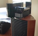
The current state of affairs: Works like a charm.
Attachments
- Status
- Not open for further replies.
- Home
- Amplifiers
- Solid State
- 1000 Watt Sub Amp: Design / Build