Either have to keep the inductor small (mH) or use a split inductor and put each half in one of the DC diode pathes. I don't believe a common mode inductor made from an un-gapped xfmr will work, since it doesn't store any energy that way.
Previous experiments using a CT power transformer and FW bridge to make positive and negative supplies showed a large ripple reduction using an old power transformer as a common mode choke. The phasing needs to be correct and the DC load currents need to be equal for an ungapped transformer to avoid saturation.
How much current were you able to draw that way?
Seems to me that if the DC currents cancel (common mode) it has high inductance (with no gapping) and acts almost like an open circuit. It the DC currents don't cancel, it saturates and acts like a short circuit.
Seems to me that if the DC currents cancel (common mode) it has high inductance (with no gapping) and acts almost like an open circuit. It the DC currents don't cancel, it saturates and acts like a short circuit.
Last edited:
How much current were you able to draw that way?
I have been doing this to make + and - 150 volts from an isolation transformer to run two PowerDrive circuits. Total AVERAGE current is about 40 mA. The current increases as a grid is driven into A2, and the DC does get unbalanced as some current is diverted into the grid. A 330 uF cap across each output seems to avoid issues. Input caps are 47uF. The transformer and the choke are both cheap Triad N-68X's.
I'm thinking about wiring two of the $15 transformers together to run a red board. No V doubler, since I plan on cranking this thing to at least 100 WPC.
Considering just the cost of supporting caps and chokes to
rig up a doubler that doesn't suck, throwing another $15
anvil (or two) at the problem is probably cheaper. Maybe
lighter too, depending what size chokage were considering.
The only chokes I got right now are 10H Hammond monsters,
and tiny RF chokes... Neither really suitable for partial PFC.
But if I were to string up all three anvils 660VAC, full wave
rectify into the Hammond choke (tiny snubber cap on input).
What Volts do I expect to get after the choke smoothage?
Is it 660VDC or 440VDC? I forget the maths, and not set up
for LTSpice right this sec...
Last edited:
Is it 660VDC or 440VDC? I forget the maths, and not set up
for LTSpice right this sec...
Most choke input filters deliver about the same DC volts out as AC volts in, sometimes slightly less. It depends on the size of your "snubber" cap, and your ability to maintain "critical current" in an AB amp.
Another consideration is the voltage breakdown of the windings. Wiring 3 of these guys in series will impress a pretty serious voltage stress across the transformers. If you do this make sure that all metal on the entire amp is grounded (should be SOP). These transformers are of unknown vintage, and storage conditions.
Back in high school electronics class I used to wire several 400 volt Eico power supplies in series to get more voltage for my "experiments". One day a power supply burst into flames. The power transformer had arced internally. "Someone" had wrapped the fuse with aluminum foil. The teacher was not amused.
I have wired two of these in series without fireworks, but the transformers were cold and it was a quick test. I'M figuring two anvils, two FWB's two chokes, some small electrolytics, and two giant 600uF 500V ASC caps scored on Ebay should make two 330 volt supplies which I will wire in series, and feed into the red board. I will wire the two 40 volt windings in series to make a -100 volt bias supply. I think I can light up some 35LR6's with some combination of all those filament winding.
I didn't find it particularly hard to rig up a doubler with a transformer that was designed for that purpose, and no. it didn't suck. I may try a doubler on one the transformers that are coming in the mail, with the intention of doing a 6HV5A Schade -style Class A2 amplifier.
My doubler sim looks fine, smooth and quickly damped on the amplifier side.
Rises to 425, falls to 400, after 200mS flat as a pancake... Its what 1.6A
secondary spikes do? That still has me concerned... Maybe just a lack of
hands-on experience with big iron, misunderestimating imaginary problems.
Rises to 425, falls to 400, after 200mS flat as a pancake... Its what 1.6A
secondary spikes do? That still has me concerned... Maybe just a lack of
hands-on experience with big iron, misunderestimating imaginary problems.
1.6A secondary spikes do - what they do. If the power train is is sized to take it, nothing untoward happens. Designers of cheap SMPS have been living with this for years. If the Euro-bureaucrats have their way, though, not for much longer.
I don't go crazy with doublers myself, but if I'm trying to build an amp with Fisher/Scott iron that worked with a doubler, that's the way I go rather than pitching the power transformer for a new one.
I don't go crazy with doublers myself, but if I'm trying to build an amp with Fisher/Scott iron that worked with a doubler, that's the way I go rather than pitching the power transformer for a new one.
I didn't find it particularly hard to rig up a doubler with a transformer that was designed for that purpose....Its what 1.6A secondary spikes do? That still has me concerned...
The Ebay ad for these transformers stated that they were intended to run a voltage doubler for use in a 120 watt amplifier. I would therefore assume that they would work fine in that application.
I am not building a 120 watt amplifier. I think the proper operating point for Petes magic red board should be about 100 WPC. This means two transformers, so no doubler.
I have a bigazz power transformer liberated from an old Zenith TV set. It used a voltage doubler. I will post a picture of it when I get a chance. Lets just say that it was the last of a dying breed. Ever seen heat sink fins on a consumer grade power transformer?
Afterthought engineering?
Why wouldn't they just design the transformer not to need heat sinks in the first place?
Or is this a matter of thermal management where a transformer (like most any component) can have it's rating increased by adding a heat dissipation mechanism?
Why wouldn't they just design the transformer not to need heat sinks in the first place?
Or is this a matter of thermal management where a transformer (like most any component) can have it's rating increased by adding a heat dissipation mechanism?
...can have it's rating increased by adding a heat dissipation mechanism?
Exactly.
By the way, I received mine today. Very fast shipment!
Going to try them...
Got mine today - the box looks like it's been through a war, with obvious drop damage.
Edit - Paraphrasing Mr. Rogers, can you say, "ugly boat anchor?"
Edit - Paraphrasing Mr. Rogers, can you say, "ugly boat anchor?"
Last edited:
I received one of each type yesterday (#7018 and #7019). I guess I wasn't paying attention to the "ten pounds" part, because I was surprised by the weight and size of these guys. It seems a shame I'm only going to run a pair of 6BM8 off the lower voltage one. I'll be using a full wave solid state bridge, so no doubler for me. I'm not sure what I'm going to do with the higher voltage one.
They both arrived in perfectly good condition. While the cloth jacketed leadouts are clearly a half century old, it's surprising how clean and flexible they are.
They both arrived in perfectly good condition. While the cloth jacketed leadouts are clearly a half century old, it's surprising how clean and flexible they are.
I will use them for monoblocks. They look like were dipped in asphalt. I've found a PS chassis already, it is a Netra T1 PS. 😀
Afterthought engineering? Why wouldn't they just design the transformer not to need heat sinks in the first place?
Which costs more, building a bigger transformer, or putting a few fins on a smaller one?
In my younger days I got all my parts from old TV's, radios, and HiFi sets. So did many experimenters. The word was out that the transformers from Zenith TV's were the one to use in ham transmitters, guitar amps, and anything else where serious abuse was the norm.
In high school I got a job in a TV repair shop fixing TV's. This was 1960's Miami where only rich people had air conditioning. TV sets got HOT and transformers fried. Customers that taped the reset button down didn't help. Philco, RCA, GE (junk) Magnavox....Fried. I never changed the power transformer in a Zenith or a Sylvania. GE TV's had some new fangled plastic inside the high voltage box. Add some Florida heat and humidity, and a good bit of dust and the lightning bolts started flying. The plastic carbon tracks and then burns!
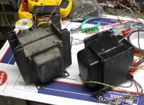
The picture shows a transformer I ripped from a Zenith color TV on the side of the road using only a pair of pliers and a jack handle. I had to whack on it a bit, but it works just fine. Yes, it used a voltage doubler. It also had a tap on the primary to run the series string heaters and a 6.3 volt winding for a few tubes and the CRT. The date on it is 1969. This is about the end of the power transformer era. The fins on this transformer are bolted on after construction and the entire assembly is dipped in epoxy. The earlier transformers had an oversized lamination every 1/4 inch or so for the fins.
The other transformer in the picture is one of the 10 pounders.
Attachments
I see there is a 160/200 watt OPT from same maker Woodward Schumaucher from the 1970's, NOS. It is not cheap though, the guy seems to be taking offers around $80 or less. 5K primary, 4 and 8 ohms out. Designed for guitar amps. Don't know if it actually made it into a Fender production model. Ebay Item no. 110268290224. Looks like about 10lbs too. He's sold a heap of 'em.
BTW George thanks for letting us know about the bargain 10 pounder, fantastic😀
BTW George thanks for letting us know about the bargain 10 pounder, fantastic😀
Ahhh, looks like it was used in a 160W PA amp with 2 "special" 6550 tubes and 700V B+ using a voltage doubler. Looks like they are pulling 350V from the junction of the caps to supply the rest of the amp with B+ including the screens.
http://www.prowessamplifiers.com/schematics/fender/ps160.pdf
http://www.prowessamplifiers.com/schematics/fender/ps160.pdf
Last edited:
I see there is a 160/200 watt OPT from same maker Woodward Schumaucher from the 1970's, NOS. It is not cheap though
The OPT is indeed a Schumaker from the 80's. The ones that I have are rated for "80 VA" over the range of 70 Hz to 4 KHz. They are 6600 ohms with 4, 8 and 16 ohm taps. They weigh 5 pounds each. I bought about 200 of them 15 years ago for $16 each! I was making guitar amps then.
These went to ADA (says so on the shipping boxes). I am not sure the amp ever made it into production before ADA went out of business. They were made for guitar amps and have no interleaving at all (I took one apart). They do sound quite nice in HiFi amps. If you want 20 Hz to 20 KHz without saturation you need to limit the power to about 25 watts. If you have speakers like mine that don't go below 70 Hz, then 75 watts is OK. I use them in amps from the Simple P-P to the 300Beast with good results. I have extracted over 200 watts from sweep tubes through these transformers at 600 volts and 3300 ohms with decent results and no fireworks.
I bought some from the owner, paid $25 for each. Used in first Pyramid amps, with paralleled 6P3S tubes for 40W only output for Hi-fi. Surprisingly nice response. They indeed were used in ADA amps, I met the owner (designer), his name was AFAIR David. He said, he was selling the rest survived after the fire on the plant in Oakland. He had a site adadepot.com where he supported amps he sold to happy guitarists. Some of his tube amps had MIDI control.
I got mine from an Ebay seller in North Carolina who built guitar amps. He had about 1000 of them. It is not clear whether these were ever delivered to ADA or sold as surplus by Schumaker. They were in Schumaker shipping cartons, packed 8 to a box.
I have an ADA MP-1 Midi controlled guitar preamp using two Sovtek 12AX7's. It is at least a 10 year old design, but works good for what it is. Quite microphonic though.
I use it for "stress testing" my amplifier designs. I dial up a mega overloaded Marshall stack preset, connect the output of the MP-1 up to the amp being tested, plug in my guitar and wail away. This method has found the weak links in a few amplifier designs that wasn't seen in "normal" use.
Some of his tube amps had MIDI control.
I have an ADA MP-1 Midi controlled guitar preamp using two Sovtek 12AX7's. It is at least a 10 year old design, but works good for what it is. Quite microphonic though.
I use it for "stress testing" my amplifier designs. I dial up a mega overloaded Marshall stack preset, connect the output of the MP-1 up to the amp being tested, plug in my guitar and wail away. This method has found the weak links in a few amplifier designs that wasn't seen in "normal" use.
- Status
- Not open for further replies.
- Home
- Amplifiers
- Tubes / Valves
- 10 pounds of power for $15