Tar on them is functional. I don't want to remove it. May be use some heatgun to make it smooth and even.
since this is a rambling thread anyway....
Michale Koster, can you tell us more about this....
>>>I can't afford to run an amp like this on a daily basis due to the power consumption and my limited off-grid power resources<<<
always interested in alternative energy sources....
Thanx!
Michale Koster, can you tell us more about this....
>>>I can't afford to run an amp like this on a daily basis due to the power consumption and my limited off-grid power resources<<<
always interested in alternative energy sources....
Thanx!
Not to highjack this thread...
Does anyone have some tips on how to get this combo going that i just bought?
steve red board
6hj5
2 of these transformers
I know i need to swap g1 and g2 on the board, and upgrade the electrolytics to handle the voltage. If im shooting for quality do i want 6k or 3.3k primaries(im only looking for 50 watts or less due to output iron cost)?
I think tube lab said just wire 1 transformer normal to the board and then wire the other transformer, rectified/filtered in the same way, i series to the power tubes to double the voltage.
Do i have to upgrade any parts on the red board? swap anything to a higher wattage?
Does anyone have some tips on how to get this combo going that i just bought?
steve red board
6hj5
2 of these transformers
Give me a week or two. I have exactly the same combo in mind, but some experiments are needed first to determine the load needed for the B+ voltage 2 of these transformers will generate. I'm guessing that a load in the 6600 ohm range will be capable of over 100 watts on a B+ of 650 to 750 volts.
My wife has been spending much of her time 1200 miles away caring for her mother who has cancer. She got three weeks at home, so no Tubelab for 3 weeks. My other life will resume late next week.
Do i have to upgrade any parts on the red board? swap anything to a higher wattage?
Some resistor values are changed, and the feedback resistors need to be made from a series connection of 2 or 3 resistors since they will see over 1000 volts on signal peaks.
I will post the build up of this amp in the red board thread when it resumes.
I like the space and weight savings due to the SMPS, as well as the stiffer B+.
Good man....like me, SMPS is streets forward.
richy
I like to watch people try to steal a 50 pound amp...
Sweet a tube amp, this will be worth a bundle, Hurgggghhhh!!!!!!
Hell whit it, grab the 36" tv, its ligher
Sweet a tube amp, this will be worth a bundle, Hurgggghhhh!!!!!!
Hell whit it, grab the 36" tv, its ligher
Ok i got my 30 pounds for $70 (he upped the price to 20 a pop)
These things have been hit hard by the ugly stick. The end bells could be removed and painted, but the copper has been old school soldered on top, and theres lots of thick black on on them.
http://img828.imageshack.us/img828/5009/p1010283c.jpg
http://img169.imageshack.us/img169/9618/p1010284x.jpg
http://img258.imageshack.us/img258/2774/p1010285z.jpg
I can take more picks if any one wants some action shots or something
These things have been hit hard by the ugly stick. The end bells could be removed and painted, but the copper has been old school soldered on top, and theres lots of thick black on on them.
An externally hosted image should be here but it was not working when we last tested it.
An externally hosted image should be here but it was not working when we last tested it.
An externally hosted image should be here but it was not working when we last tested it.
http://img828.imageshack.us/img828/5009/p1010283c.jpg
http://img169.imageshack.us/img169/9618/p1010284x.jpg
http://img258.imageshack.us/img258/2774/p1010285z.jpg
I can take more picks if any one wants some action shots or something
Last edited:
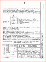
Ahhh, looks like it was used in a 160W PA amp with 2 "special" 6550 tubes and 700V B+ using a voltage doubler. Looks like they are pulling 350V from the junction of the caps to supply the rest of the amp with B+ including the screens.
http://www.prowessamplifiers.com/schematics/fender/ps160.pdf
Uh, everything else supplied 350V from mid-doubler?
Wouldn't that cause a large DC in the secondary?
Just how many mA of DC we talking here?
12AX7 (V1,2,3,4,6) , 12AT7 (V5), 6V6 (V8)
And all screens including 6550 (V9,10)
DC cheat obviously must have worked I'spos?
Still amazing whats routinely got away with...
Dis here must be one hard to kill lump of iron.
Hope they least had sense to phase opposite
of bias winding's half wave DC.
They ain't flirtin with saturation for subtle wack
reason of regulation I just don't get quite yet?
Are they??? No, couldn't be....
Last edited:
Here's the OPT #010490 for that Fender amp:
Fender OPT on ebay
I wonder if the driver iron 010491 is up for sale somewhere😉
More to the point
This PT and circuit (I just got 2 for myself also) with an Edcor CXPP 5K/100W OPT and a pair of good 6550s using a DCPP type circuit would make a killer ~100W monoblock. A buck transformer might be needed to reduce the B+just a little for available 6550s.
It does seem like there will be a half wave current imbalance. I wonder if it's gapped?
Last edited:
These things have been hit hard by the ugly stick.
Power transformers never needed to be pretty until recently 🙄
Power transformers never needed to be pretty until recently 🙄
I take it your from the camp "if its not bound in pleather/carpet its not a real amp crowd" 🙂
Im from "if its not black, its not an amp" group
That OPT is near identical physical size to the 10 pound power tranny in this thread. 😱
I have a pair of those monsters. The measure out at 7k P-P for an 8 ohm load, so they will take 700-800v of B+ to deliver the stated power rating. They're big enough for the job, though, and somewhat better looking than your average Hammond monster (if you like black, that is).The power transformers, however, got a thorough whippin' with the ugly stick....
Last edited:
Hey mine didn't get whipped with that ugly stick, I might have to send them back for some treatment 😀
I have a pair of those monsters. The measure out at 7k P-P for an 8 ohm load, so they will take 700-800v of B+ to deliver the stated power rating. They're big enough for the job, though, and somewhat better looking than your average Hammond monster (if you like black, that is).The power transformers, however, got a thorough whippin' with the ugly stick....
The datasheet says 5K primary impedance. Is it the same transformer?
The Fender amp that used this OPT had 700V B+ and was rated at 160W Po😱 with only a pair of 6550s
Attachments
If you closely peruse the data sheet, it's rather elastic as to output impedance. If you load with one impedance inside the range specified you can get 5k. If you load with 8 ohms, you get 8k. I tested the turns ratio, which is the real determiner of impedance.
If you closely peruse the data sheet, it's rather elastic as to output impedance. If you load with one impedance inside the range specified you can get 5k. If you load with 8 ohms, you get 8k. I tested the turns ratio, which is the real determiner of impedance.
Sure enough. The amp schematic shows 2.6 ohms speaker load connected to the shorter winding. Maybe someone marked up the datasheet with the conflicting impedance numbers... How does the frequency response of these measure?
Thanks!
Didn't measure that... However, if I use them in a biamped setup, I can use a very nice tweeter amp. The primary inductance was pretty huge, so I suspect that at least the low end is ok.
- Status
- Not open for further replies.
- Home
- Amplifiers
- Tubes / Valves
- 10 pounds of power for $15