Hi all
Time to share a further model of mine...
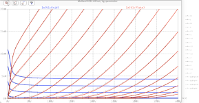
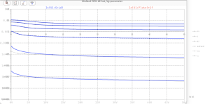
This time, the EC91 - a very strong tube for its large mu.
Enjoy!
BR Adrian
Time to share a further model of mine...
This time, the EC91 - a very strong tube for its large mu.
Enjoy!
BR Adrian
Code:
*EC91 LTspice model based on the generic triode model from Adrian Immler, version i6
*A version log is at the end of this file
*100h BurnIn of 10 Mullard tubes, sample selection and measurements done in June 2024
*Params fitted to the measured values by Adrian Immler, June 2024
*This model is accurate for Vg up to 1.5V.
*The fit quality is presented at adrianimmler.simplesite.com
*History's best of tube describing art (plus some new ideas) is merged to this new approach.
*@ neg. Vg, Ia accuracy is similar to Koren models, and unrivaled for remote cutoff triodes
*@ small neg. Vg, the "Anlauf" current is considered.
*@ pos. Vg, Ig and Ia accuracy is on an unrivaled level (including neg. Va range!)
*This offers new simulation possibilities like grid resistor bias, backward plate modulated stages,
*Audion radio circuits, low voltage amps, guitar distortion stages or pulsed stages.
*It is assumed that there exists only 1 construction version of the EC91 (3 different brands seen so far)
*Hence, the two letters for the brand are skipped.
*            i6 version is identical to the i5, but measurements done with HOT anode for highest accuracy
*            |  anode (plate)
*            |  | grid
*            |  | | cathode
*            |  | | |
.subckt EC91.i6 A G K
+ params:
*Parameters for space charge current Is (100% assigned to Ia @ Vg < 0)
+ mu   = 96    ;Determines the voltage gain @ constant Ia
+ rad  = 9k    ;Differential anode resistance, set @ Iad and Vg=0V
+ Vct  = 0.49  ;Offsets the Ia-traces on the Va axis. Electrode material's contact potential
+ kp   = 350   ;Mimics the island effect
+ xs   = 1.5   ;Determines the curve of the Ia traces. Typically between 1.2 and 1.8
+ kIsr = 114m  ;Va-indepedent part of the Is reduction when gridcurrent occurs
+ kvdg  = 75   ;Va-depedent part of the Is reduction when gridcurrent occurs
*
*Parameters for assigning the space charge current to Ia and Ig @ Vg > 0
+ kB   = 0.5   ;Describes how fast Ia drops to zero when Va approaches zero.
+ radl = 630   ;Differential resistance for the Ia emission limit @ very small Va and Vg > 0
+ tsh  = 7     ;Ia transmission sharpness from 1th to 2nd Ia area. Keep between 3 and 20. Start with 20.
+ xl   = 1.3   ;Exponent for the emission limit
*
*Parameters of the grid-cathode vacuum diode
+ kg = 390     ;Inverse scaling factor for the Va independent part of Ig (caution - interacts with xg!)
+ Vctg = 0.06  ;Offsets the log Ig-traces on the Vg axis. Electrode material's contact potential
+ xg   = 1.15  ;Determines the curve of the Ig slope versus (positive) Vg and Va >> 0
+ VT   = 0.115 ;Log(Ig) slope @ Vg<0. VT=k/q*Tk (cathodes absolute temp, typically 1150K)
+ rTr  = 0.7   ;ratio of VT for Igr. Typically 0.8
+ kVT  = 8m    ;Va dependant koeff. of VT
+ gft1 = 0.02  ;reduces the steering voltage around Vg=-Vg0, for finetuning purposes
+ gft1a= 0.05  ;reduces the steering voltage around Vg=-Vg0. Effect decreases with 1/(1+kB*Va)
+ gft2 = 1     ;finetunes the Igr drop @ incrasing Va and around Vg=-Vg0
*
*Parameters for the caps
+ cag  = 2p5   ;From datasheet
+ cak  = 0p2   ;From datasheet
+ cgk  = 8p5   ;From datasheet
*
*special purpose parameters
+ os = 1       ;Overall scaling factor, if a user wishes to simulate manufacturing tolerances
+ murc = 10    ;Mu of the remote cutoff triode
+ ksrc = 10G   ;Inverse Iarc gain factor for the remote cuttoff triode
+ kprc = 1k    ;Mimics the island effect for the remote cotoff triode
+ Vbatt = 0    ;heater battery voltage for direct heated battery triodes
+ Vdrmax = 1   ;max voltage of internal Vg drop, for convergence improvements
*
*Calculated parameters
+ Iad = {100/rad} ;Ia where the anode a.c. resistance is set according to rad.
+ ks = {pow(mu/(rad*xs*Iad**(1-1/xs)),-xs)} ;Reduces the unwished xs influence to the Ia slope
+ ksnom = {pow(mu/(rad*1.5*Iad**(1-1/1.5)),-1.5)} ;Sub-equation for calculating Vg0
+ Vg0 = {Vct + (Iad*ks)**(1/xs) - (Iad*ksnom)**(2/3)} ;Reduces the xs influence to Vct.
+ kl = {pow(1/(radl*xl*Ild**(1-1/xl)),-xl)} ;Reduces the xl influence to the Ia slope @ small Va
+ Ild = {sqrt(radl)*1m} ;Current where the Il a.c. resistance is set according to radl.
*
*Space charge current model
Rak A K 100G ;avoids "floating net" errors
Bft   ft 0 V=1/(1+pow(2*abs(v(G,Ki)+Vg0),3)) ;an auxiliary voltage to finetune the triode around Vg=-Vg0
Bggi GGi 0 V=(v(Gi,Ki)+Vg0)*(1/(1+kIsr*max(0, v(G,Ki)+Vg0))) - gft1*v(ft) - gft1a*v(ft)/(1+kB*v(Ahc)) ;Effective internal grid voltage.
Bahc Ahc 0 V=uramp(v(A,Ki)) ;Anode voltage, hard cut to zero @ neg. value
Bst   St 0 V=uramp(max(v(GGi)+v(A,Ki)/(mu), v(A,Ki)/kp*ln(1+exp(kp*(1/mu+v(GGi)/(1+v(Ahc)))))));Steering volt.
Bs    Ai Ki I=os/ks*pow(v(St),xs) ;Langmuir-Childs law for the space charge current Is
*Bstrc Strc 0 V=uramp(max(v(GGi)+v(Ahc)/(murc), v(Ahc)/kprc*ln(1+exp(kprc*(1/murc+v(GGi)/(1+v(Ahc)))))));FOR REMOTE CUTOFF TUBES ONLY
*Bsrc   Ai Ki I=os/ksrc*pow(v(Strc),xs) ;FOR REMOTE CUTOFF TUBES ONLY
*
*Anode current limit @ small Va
.func smin(z,y,n) {pow(pow(z+1f, -n)+pow(y+1f, -n), -1/n)} ;Min-function with smooth trans.
.func ssmin(z,y,n) {min(min(z,y), smin(z*1.003,y*1.003,n))};smin-function which suppresses small residual differencies
Ra  A Ai 1
Bgl Gi A I=uramp(i(Ra)-ssmin(1/kl*pow(v(Ahc),xl),i(Ra),tsh)) ;Ia emission limit
*
*Grid model
Rgk G K 10G ;avoids "floating net" errors
Bvdg G Gi I=1/kvdg*pow(v(G,Gi),1.5) ;Reduces the internal effective grid voltage when Ig rises
Bcoh G Gi I=pow(uramp(v(G,Gi)-Vdrmax),2) ;A convergence help which softly limits the internal Vg voltage drop.
Rgip G Gi 1G ;avoids some warnings
.func fVT() {VT*exp(-kVT*sqrt(v(A,Ki)))}
.func Ivd(Vvd, kvd, xvd, VTvd)  {if(Vvd < 3, 1/kvd*pow(VTvd*xvd*ln(1+exp(Vvd/VTvd/xvd)),xvd), 1/kvd*pow(Vvd, xvd))} ;Vacuum diode function
Bgvd G Ki I=Ivd(v(G,Ki) + Vctg + min(0,v(A,Ki)/mu), kg/os, xg, fVT()) ;limits the internal Vg for convergence reasons
Bstn Stn 0 V=v(GGi)+min(0,v(A,Ki))/mu ;special steering voltage, sensitive to negative Anodevoltages only
Bgr Gi Ai I= ivd(v(Stn),ks/os, xs, rTr*fVT())/(1+(kB+v(ft)*gft2)*v(Ahc));Is reflection to grid when Va approaches zero
*Bgr Gi Ai I=(ivd(v(Stn),ks/os, xs, rTr*fVT())+os/ksrc*pow(v(GGi),xs))/(1+(kB+v(ft)*gft2)*v(Ahc));FOR REMOTE CUTOFF TUBES ONLY
Bs0 Ai Ki  I=uramp(ivd(v(Stn),ks/os, xs, rTr*fVT()) - os/ks*pow(v(Stn),xs))
Bbatt Ki K V=Vbatt/2 ;for battery heated triodes; Offsets the average cathode potential to the half heater battery voltage
*
*Caps
C1 A G {cag}
C2 A K {cak}
C3 G K {cgk}
.ends
*
*Version log
*i1 :Initial version
*i2 :Pin order changed to the more common order A G K (Thanks to Markus Gyger for his tip)
*i3 :bugfix of the Ivd-function: now also usable for larger Vvd
*i4: Rgi replaced by a virtual vacuum diode (better convergence). ft1 deleted (no longer needed)
;2 new prarams for Ig finetuning @ Va and Vg near zero. New overall skaling factor os for aging etc.
*i5: improved convergence performance. PosVg/NegVa area now correct. Also accurate now for remote cutoff triodes!
*i6: identical to the i5, but tubes measured with hot anode (Pa=0.7*Pmax) for highest accuracy
Attachments

Looking for a spice model for 4D32/4D22. Pentode mode is good for me. I saw someone asked for this in 2018, but didn’t see a model posted. Thanks!
Hi,
Just looking for LTspice models for the following tubes:
1. EY88 (philips)
2. 6AW8 (RCA)
3. 8552 (RCA)
Anyone can help?
Thanks a lot.
Just looking for LTspice models for the following tubes:
1. EY88 (philips)
2. 6AW8 (RCA)
3. 8552 (RCA)
Anyone can help?
Thanks a lot.
Hi all
Time to share a further model of mine...
This time, the EC91 - a very strong tube for its large mu.
Enjoy!
BR Adrian
Thank you Adrian. I gave it a spin in LTspice XVII and it worked just fine. Interesting triode too. Unfortunately, its Cag is quite high, so even though it's a strong candidate for a phono stage input triode in every other way, its input capacitance is likely to cause problems with many MM cartridges. It does look linear enough to be used as the second stage in a phono stage, or perhaps as the input amplifier stage for a power amp.
Hi rongon
Thanks for this interesting insight regarding Cag. I recently thought „Why even mention in tube spice models - not of relevance for audio“ but now learned that it can even „sacrify“ a phono stage…
Thanks for this interesting insight regarding Cag. I recently thought „Why even mention in tube spice models - not of relevance for audio“ but now learned that it can even „sacrify“ a phono stage…
Cag gets multiplied by in-circuit mu (miller effect). If mu is 80 x 2.5pF + cable and wiring would load the cartridge with some 300pF. Most MM specs say 100pF ...
No problem in cascode though or folded cascode.
No problem in cascode though or folded cascode.
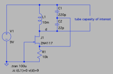
BTW - when a pentode is used as in triode-connected mode, one typically face the issue that the corresponding miller capacity from g1 to g2+a is missed in the data sheet. So, for a complete spicemodel, one needs to measure it. I did so for the Siemens 6U8A pentode model I provided recently.
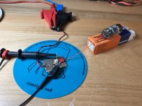
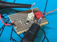
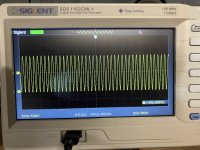
But how to measure this when no suitable measurement tool is available?
A "poor mens" method to solve that is to solder together an LC based oscillator, and measure its frequency with and without connected tube. This way, one can calculate the capacity of interest.
This was a nice "rainy day" project that I really enjoyed!
Attachments
Thanks a lot.6AW8 Small Signal Triode:
The file contains two models:
6AW8_T1 which is derived from the large signal curves in the GE data sheet
6AW8_T2 which is derived from the small signal curves
6AW8 Pentode model
Hi Adrian,Hi Frederico
One should distinguish between models for vacuum diodes, triodes and tetrodes/pentodes.
For vacuum diodes and triodes, I did a detailed comparison of all important spice approaches two years ago. You will find my essay on my tube-website:
http://adrianimmler.simplesite.com/440956786
My essay will empower you to build your own opinion to that question! 😉
all the best, Adrian
I recently came across your paper on valve modelling history and would like to thank you for your work. Like you, I've experimented with a version of the uTracer as a consequence of reading Merlin Blencowe's work on valvewizard.co.uk, which then led me to Derk Reefman's work on valve modelling. As someone who dabbles in guitar amplifiers at more usual values of HT, I've never needed to explore the behaviour of valves with a positive grid drive or model grid current but the modelling is very interesting. I've used Ceres Solver to explore modelling measured devices and have added a few refinements (imho) to Reefman's models to include:
- unifying his two pentode models (true pentode and beam tetrode) by introducing a "knee sharpness" variable within a single function
- allowing the position of the pentode knee to be influenced by Vg1 (which definitely improves the fit)
- a set of dedicated screen parameters to improve fit to measured screen currents (although I would love to be able to pin down the physics to explain this)
In case it's of any interest, my take on modelling is described here: https://whitecottage.org.uk/guitar-and-audio/valve-modelling/
Btw, your site on simplesite seems to be down currently.
Thanks again
Hi olivergardiner6
Thanks for your hints, regarding my site as well regarding your work on tube models. I will add it to my collection of tube spice model approaches. I'm pleased to see that tube spice model development is still ongoing!
Derk Reefmans approach for Secondary Emission was my starting point to develop my own approach, used e.g. in my 6L6 model. For Pentodes, I prefer Ayumis model compared to Derk's because they are universal (like mine), meaning that they provide correct traces when another Vg2 voltage is used or even when G2 is connected to the plate.
Derk Reefman is strong in providing fundamental stuff like he did for remote cutoff (or variable mu) tubes. Also here, my models are based on his fundaments and adapted to my own approach, resulting in tube models for PC97 and ECC189 remote cutoff mu tubes.
BR Adrian
Hi olivergardiner6
Regarding my website - I can‘t see any issue. May I ask you what browser and OS you use?
BR Adrian
Regarding my website - I can‘t see any issue. May I ask you what browser and OS you use?
BR Adrian
Hi Adrian,
Indeed it certainly works now - on Monday it was just showing a plain text representation of the menus without formatting down the left hand side and no content at all (Chrome/Edge). I'd assumed you'd applied a fix but it sounds like it was a simplesite problem that they've now fixed themselves.
Cheers,
Oliver
Tube spice models.

Code:
.SUBCKT RS1003-300 P G2 G K ; LTSpice tetrode.asy pinout
* .SUBCKT RS1003 _300V P G K G2 ; Koren Pentode Pspice pinout
+ PARAMS: MU=25.09 KG1=242 KP=120.13 KVB=12 VCT=0.2 EX=1.244 KG2=8022 KNEE=21.22 KVC=2.57
+ KLAM=9.72E-6 KLAMG=2.362E-4 KNEE2=20 KNEX=30  KNK=-0.044 KNG=0.006 KNPL=50 KNSL=11 KNPR=120 KNSR=29
+ CCG=3P CGP=1.4P CCP=1.9P RGI=2000.0
* Vp_MAX=1000 Ip_MAX=1200 Vg_step=4 Vg_start=20 Vg_count=9
* X_MIN=398 Y_MIN=42 X_SIZE=520 Y_SIZE=563 FSZ_X=1382 FSZ_Y=754 XYGrid=false
* Rp=3122 Vg_ac=20 P_max=60 Vg_qui=4 Vp_qui=23.22
* showLoadLine=y showIp=y isDHP=n isPP=n isAsymPP=n isUL=n showDissipLimit=y
* showIg1=n isInputSnapped=y addLocalNFB=n
* XYProjections=n harmonicPlot=y dissipPlot=n
* UL=0.43 EG2=300 gridLevel2=n addKink=y isTanhKnee=y advSigmoid=n
*----------------------------------------------------------------------------------
RE1  7 0  1G    ; DUMMY SO NODE 7 HAS 2 CONNECTIONS
E1   7 0  VALUE=  ; E1 BREAKS UP LONG EQUATION FOR G1.
+{V(G2,K)/KP*LN(1+EXP((1/MU+(VCT+V(G,K))/SQRT(KVB+V(G2,K)*V(G2,K)))*KP))}
RE2  6 0  1G    ; DUMMY SO NODE 6 HAS 2 CONNECTIONS
E2  6 0  VALUE={(PWR(V(7),EX)+PWRS(V(7),EX))} ; Kg1 times KIT current
RE21 21 0 1
E21  21 0 VALUE={V(6)/KG1*ATAN((V(P,K)+KNEX)/KNEE)*TANH(V(P,K)/KNEE2)} ; Ip with knee but no slope and no kink
RE22 22 0 1 ; E22: kink curr deviation for plate
E22  22 0 VALUE={V(21)*LIMIT(KNK-V(G,K)*KNG,0,0.3)*(-ATAN((V(P,K)-KNPL)/KNSL)+ATAN((V(P,K)-KNPR)/KNSR))}
G1   P  K  VALUE={V(21)*(1+KLAMG*V(P,K))+KLAM*V(P,K) + V(22)}
* Alexander Gurskii screen current, see audioXpress 2/2011, with slope and kink added
RE43 43 K 1G ; Dummy
E43  43 G2 VALUE={0} ; Dummy
G2   43 K  VALUE={V(6)/KG2*(KVC-ATAN((V(P,K)+KNEX)/KNEE)*TANH(V(P,K)/KNEE2))/(1+KLAMG*V(P,K))-V(22)}
RCP  P K  1G     ; FOR CONVERGENCE
C1   K G  {CCG}  ; CATHODE-GRID 1
C2   G P  {CGP}  ; GRID 1-PLATE
C3   K P  {CCP}  ; CATHODE-PLATE
R1   G 5  {RGI}  ; FOR GRID CURRENT
D3   5 K  DX     ; FOR GRID CURRENT }
.MODEL DX D(IS=1N RS=1 CJO=10PF TT=1N)
.ENDS- Home
- Amplifiers
- Tubes / Valves
- Vacuum Tube SPICE Models