Hi DSU
This paper of mine might be interresting for you:
https://drive.google.com/file/d/1CF61JpKPAK8pFmsGam4kmcbCehU1qxJz/view
BR Adrian
This paper of mine might be interresting for you:
https://drive.google.com/file/d/1CF61JpKPAK8pFmsGam4kmcbCehU1qxJz/view
BR Adrian

45 SPICE Models
Code:
**** * ******************************************
* Created on 06/04/2024 18:02 using paint_kit.jar 3.1
* www.dmitrynizh.com/tubeparams_image.htm
* Plate Curves image file: *.jpg
* Data source link:
*----------------------------------------------------------------------------------
.SUBCKT 45 1 2 3 ; Plate Grid Cathode
+ PARAMS: CCG=4P  CGP=7P CCP=3P RGI=2000
+ MU=3.654 KG1=2640 KP=46 KVB=34.88 VCT=3.125E-4 EX=1.302
* Vp_MAX=500 Ip_MAX=75 Vg_step=10 Vg_start=0 Vg_count=14
* Rp=6307.47 Vg_ac=20.92 P_max=10 Vg_qui=-189.71 Vp_qui=474.63
* X_MIN=14 Y_MIN=75 X_SIZE=348 Y_SIZE=210 FSZ_X=1260 FSZ_Y=630 XYGrid=false
* showLoadLine=y showIp=y isDHT=n isPP=n isAsymPP=n showDissipLimit=y
* showIg1=n gridLevel2=n isInputSnapped=n
* XYProjections=n harmonicPlot=n dissipPlot=n
*----------------------------------------------------------------------------------
E1 7 0 VALUE={V(1,3)/KP*LOG(1+EXP(KP*(1/MU+(VCT+V(2,3))/SQRT(KVB+V(1,3)*V(1,3)))))}
RE1 7 0 1G  ; TO AVOID FLOATING NODES
G1 1 3 VALUE={(PWR(V(7),EX)+PWRS(V(7),EX))/KG1}
RCP 1 3 1G   ; TO AVOID FLOATING NODES
C1 2 3 {CCG} ; CATHODE-GRID
C2 2 1 {CGP} ; GRID=PLATE
C3 1 3 {CCP} ; CATHODE-PLATE
D3 5 3 DX ; POSITIVE GRID CURRENT
R1 2 5 {RGI} ; POSITIVE GRID CURRENT
.MODEL DX D(IS=1N RS=1 CJO=10PF TT=1N)
.ENDS
Attachments

Hello, I'm trying to make the LTspice model of the Jelabs radiotron 2a3, but I don't know if the tube models are accurate. If I use the Ayumi models plus a 6c6 model, it gives me high distortion values, but if I use tube_lib and tube_sym, 6j7 (replacement in values) and 2a3, the values are more in line with what Joe (jelabs) says.
The question would be, what would be the correct tube models to be as close to reality as possible?
I know it's not the same, but while I put the parts together to assemble the amplifier, I want to have a little fun simulating it.
I'll send you my file
thanx a lot
The question would be, what would be the correct tube models to be as close to reality as possible?
I know it's not the same, but while I put the parts together to assemble the amplifier, I want to have a little fun simulating it.
I'll send you my file
thanx a lot
Attachments
In my opinion, THD predictions from SPICE simulations should always be taken with a grain of salt.
They are useful if you have a circuit you're working with, and you have some good models to work with (I like Adrian Immler's!), and you're tweaking the circuit for lowest THD (or whatever). You can run the sim (keeping the models constant) and see which operating points result in lowest THD, etc.
Or, you can keep the models constant and try different circuit variations to see which perform best in simulation. I figure since the models remain the same, the different circuits can be directly compared.
BUT, if you change the models around, expect the results to change with them. In simulation, the exact same circuit with two different models of the same tube type can vary a lot in predicted performance.
One tube model may simulate close to reality in one particular circuit but might be very far from reality in a different circuit.
SPICE is a really valuable tool, but it's not going to tell you exactly what will happen in reality. But it will get you close in most cases.
The above is my opinion only. You are free to disagree. Thanks.
PS - It's possible the simulation results are telling you the 6J7 will work with lower THD than the 6C6. But I can't tell you for sure. Try different versions of 6C6 and 6J7 models. See if a repeatable trend emerges.
Hi all
Some weeks ago, I presented here my Siemens 6U8A Pentode model.
But the 6U8A contains also a triode - here it is, as an i6 spice model 😉.
Enjoy!
BR Adrian
PS: Be aware that most other tube manufacturer used a different construction of the 6U8A, with a very pronounced island effect for both, the pentode as well as the triode. You can easily identify this construction, as it has a large rectangular window stamped out of a sheet in the pentode construction.
Code:
*6U8A Triode LTspice model based on the generic triode model from Adrian Immler, version i6
*A version log is at the end of this file
*100h BurnIn of 10 Siemens tubes, sample selection and measurements done in Jan 2024
*Params fitted to the measured values by Adrian Immler, June 2024
*This model is accurate for Vg up to 3V.
*The fit quality is presented at adrianimmler.simplesite.com
*History's best of tube describing art (plus some new ideas) is merged to this new approach.
*@ neg. Vg, Ia accuracy is similar to Koren models, and unrivaled for remote cutoff triodes
*@ small neg. Vg, the "Anlauf" current is considered.
*@ pos. Vg, Ig and Ia accuracy is on an unrivaled level (including neg. Va range!)
*This offers new simulation possibilities like grid resistor bias, backward plate modulated stages,
*Audion radio circuits, low voltage amps, guitar distortion stages or pulsed stages.
*            Triode section
*            | SI=Siemens (Be aware of a quite different 6U8A construction with large rectangular window!)
*            | | i6 version is identical to the i5, but measurements done with HOT anode for highest accuracy
*            | | |  anode (plate)
*            | | |  | grid
*            | | |  | | cathode
*            | | |  | | |
.subckt 6U8A#T.SIi6 A G K
+ params:
*Parameters for space charge current Is (100% assigned to Ia @ Vg < 0)
+ mu   = 44    ;Determines the voltage gain @ constant Ia
+ rad  = 5k1   ;Differential anode resistance, set @ Iad and Vg=0V
+ Vct  = 0.6   ;Offsets the Ia-traces on the Va axis. Electrode material's contact potential
+ kp   = 160   ;Mimics the island effect
+ xs   = 1.5   ;Determines the curve of the Ia traces. Typically between 1.2 and 1.8
+ kIsr = 43m   ;Va-indepedent part of the Is reduction when gridcurrent occurs
+ kvdg  = 110  ;Va-depedent part of the Is reduction when gridcurrent occurs
*
*Parameters for assigning the space charge current to Ia and Ig @ Vg > 0
+ kB   = 0.45  ;Describes how fast Ia drops to zero when Va approaches zero.
+ radl = 310   ;Differential resistance for the Ia emission limit @ very small Va and Vg > 0
+ tsh  = 12    ;Ia transmission sharpness from 1th to 2nd Ia area. Keep between 3 and 20. Start with 20.
+ xl   = 1.3   ;Exponent for the emission limit
*
*Parameters of the grid-cathode vacuum diode
+ kg = 610     ;Inverse scaling factor for the Va independent part of Ig (caution - interacts with xg!)
+ Vctg = 0.02  ;Offsets the log Ig-traces on the Vg axis. Electrode material's contact potential
+ xg   = 1.15  ;Determines the curve of the Ig slope versus (positive) Vg and Va >> 0
+ VT   = 0.102 ;Log(Ig) slope @ Vg<0. VT=k/q*Tk (cathodes absolute temp, typically 1150K)
+ rTr  = 0.9   ;ratio of VT for Igr. Typically 0.8
+ kVT  = 5m    ;Va dependant koeff. of VT
+ gft1 = 0.02  ;reduces the steering voltage around Vg=-Vg0, for finetuning purposes
+ gft1a= 0.25  ;reduces the steering voltage around Vg=-Vg0. Effect decreases with 1/(1+kB*Va)
+ gft2 = 1     ;finetunes the Igr drop @ incrasing Va and around Vg=-Vg0
*
*Parameters for the caps
+ cag  = 1p8   ;From datasheet
+ cak  = 0p35  ;From datasheet
+ cgk  = 2p5   ;From datasheet
*
*special purpose parameters
+ os = 1       ;Overall scaling factor, if a user wishes to simulate manufacturing tolerances
+ murc = 10    ;Mu of the remote cutoff triode
+ ksrc = 10G   ;Inverse Iarc gain factor for the remote cuttoff triode
+ kprc = 1k    ;Mimics the island effect for the remote cotoff triode
+ Vbatt = 0    ;heater battery voltage for direct heated battery triodes
+ Vdrmax = 2   ;max voltage of internal Vg drop, for convergence improvements
*
*Calculated parameters
+ Iad = {100/rad} ;Ia where the anode a.c. resistance is set according to rad.
+ ks = {pow(mu/(rad*xs*Iad**(1-1/xs)),-xs)} ;Reduces the unwished xs influence to the Ia slope
+ ksnom = {pow(mu/(rad*1.5*Iad**(1-1/1.5)),-1.5)} ;Sub-equation for calculating Vg0
+ Vg0 = {Vct + (Iad*ks)**(1/xs) - (Iad*ksnom)**(2/3)} ;Reduces the xs influence to Vct.
+ kl = {pow(1/(radl*xl*Ild**(1-1/xl)),-xl)} ;Reduces the xl influence to the Ia slope @ small Va
+ Ild = {sqrt(radl)*1m} ;Current where the Il a.c. resistance is set according to radl.
*
*Space charge current model
Rak A K 100G ;avoids "floating net" errors
Bft   ft 0 V=1/(1+pow(2*abs(v(G,Ki)+Vg0),3)) ;an auxiliary voltage to finetune the triode around Vg=-Vg0
Bggi GGi 0 V=(v(Gi,Ki)+Vg0)*(1/(1+kIsr*max(0, v(G,Ki)+Vg0))) - gft1*v(ft) - gft1a*v(ft)/(1+kB*v(Ahc)) ;Effective internal grid voltage.
Bahc Ahc 0 V=uramp(v(A,Ki)) ;Anode voltage, hard cut to zero @ neg. value
Bst   St 0 V=uramp(max(v(GGi)+v(A,Ki)/(mu), v(A,Ki)/kp*ln(1+exp(kp*(1/mu+v(GGi)/(1+v(Ahc)))))));Steering volt.
Bs    Ai Ki I=os/ks*pow(v(St),xs) ;Langmuir-Childs law for the space charge current Is
*Bstrc Strc 0 V=uramp(max(v(GGi)+v(Ahc)/(murc), v(Ahc)/kprc*ln(1+exp(kprc*(1/murc+v(GGi)/(1+v(Ahc)))))));FOR REMOTE CUTOFF TUBES ONLY
*Bsrc   Ai Ki I=os/ksrc*pow(v(Strc),xs) ;FOR REMOTE CUTOFF TUBES ONLY
*
*Anode current limit @ small Va
.func smin(z,y,n) {pow(pow(z+1f, -n)+pow(y+1f, -n), -1/n)} ;Min-function with smooth trans.
.func ssmin(z,y,n) {min(min(z,y), smin(z*1.003,y*1.003,n))};smin-function which suppresses small residual differencies
Ra  A Ai 1
Bgl Gi A I=uramp(i(Ra)-ssmin(1/kl*pow(v(Ahc),xl),i(Ra),tsh)) ;Ia emission limit
*
*Grid model
Rgk G K 10G ;avoids "floating net" errors
Bvdg G Gi I=1/kvdg*pow(v(G,Gi),1.5) ;Reduces the internal effective grid voltage when Ig rises
Bcoh G Gi I=pow(uramp(v(G,Gi)-Vdrmax),2) ;A convergence help which softly limits the internal Vg voltage drop.
Rgip G Gi 1G ;avoids some warnings
.func fVT() {VT*exp(-kVT*sqrt(v(A,Ki)))}
.func Ivd(Vvd, kvd, xvd, VTvd)  {if(Vvd < 3, 1/kvd*pow(VTvd*xvd*ln(1+exp(Vvd/VTvd/xvd)),xvd), 1/kvd*pow(Vvd, xvd))} ;Vacuum diode function
Bgvd G Ki I=Ivd(v(G,Ki) + Vctg + min(0,v(A,Ki)/mu), kg/os, xg, fVT()) ;limits the internal Vg for convergence reasons
Bstn Stn 0 V=v(GGi)+min(0,v(A,Ki))/mu ;special steering voltage, sensitive to negative Anodevoltages only
Bgr Gi Ai I= ivd(v(Stn),ks/os, xs, rTr*fVT())/(1+(kB+v(ft)*gft2)*v(Ahc));Is reflection to grid when Va approaches zero
*Bgr Gi Ai I=(ivd(v(Stn),ks/os, xs, rTr*fVT())+os/ksrc*pow(v(GGi),xs))/(1+(kB+v(ft)*gft2)*v(Ahc));FOR REMOTE CUTOFF TUBES ONLY
Bs0 Ai Ki  I=uramp(ivd(v(Stn),ks/os, xs, rTr*fVT()) - os/ks*pow(v(Stn),xs))
Bbatt Ki K V=Vbatt/2 ;for battery heated triodes; Offsets the average cathode potential to the half heater battery voltage
*
*Caps
C1 A G {cag}
C2 A K {cak}
C3 G K {cgk}
.ends
*
*Version log
*i1 :Initial version
*i2 :Pin order changed to the more common order A G K (Thanks to Markus Gyger for his tip)
*i3 :bugfix of the Ivd-function: now also usable for larger Vvd
*i4: Rgi replaced by a virtual vacuum diode (better convergence). ft1 deleted (no longer needed)
;2 new prarams for Ig finetuning @ Va and Vg near zero. New overall skaling factor os for aging etc.
*i5: improved convergence performance. PosVg/NegVa area now correct. Also accurate now for remote cutoff triodes!
*i6: identical to the i5, but tubes measured with hot anode (Pa=0.7*Pmax) for highest accuracy
Attachments
6Z51P = 6J51P = EF184 = 6EJ7 so you can use model for 6EJ7 or EF184 if you have one.
Ale Moglia traced triode curves for a 6Z51P, if that helps...
https://www.bartola.co.uk/valves/valve-curves/6z51p-triode/
There's an EF184 model in the Ayumi collection:
https://www.diyaudio.com/community/threads/vacuum-tube-spice-models.243950/#post-3662623
Ale Moglia traced triode curves for a 6Z51P, if that helps...
https://www.bartola.co.uk/valves/valve-curves/6z51p-triode/
There's an EF184 model in the Ayumi collection:
https://www.diyaudio.com/community/threads/vacuum-tube-spice-models.243950/#post-3662623
Thanks @rongon . I have models for the 6EJ7 and EF184, but according to https://www.radiomuseum.org/tubes/tube_6j51p.html?language_id=1 it is not an identical replacement, only pretty similar.
I will compare curves Ale created with those created with the models I have.
Thanks!
I will compare curves Ale created with those created with the models I have.
Thanks!
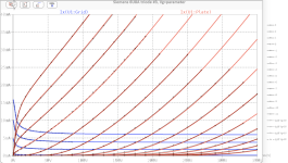
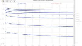
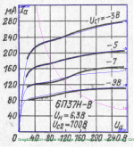
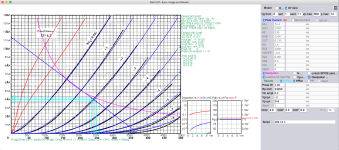
Here's a model for the 6P37N-V (6П37Н-В) Russian power beam tetrode nuvistor:
Code:
**** SCREENSHOT 2024_06_16 AT 2 ******************************************
* Created on 06/16/2024 15:08 using paint_kip.jar
* www.dmitrynizh.com/tubeparams_image.htm
* Plate Curves image file: /Users/mark/Desktop/Screenshot 2024-06-16 at 2.22.23 PM.png
* Data source link: https://lampes-et-tubes.info/rt/6P37N-V.pdf
*----------------------------------------------------------------------------------
.SUBCKT SCREENSHOT 2024_06_16 AT 2 P G2 G K ; LTSpice tetrode.asy pinout
* .SUBCKT SCREENSHOT 2024_06_16 AT 2 P G K G2 ; Koren Pentode Pspice pinout
+ PARAMS: MU=19.75 KG1=3731.2 KP=8.656 KVB=0.5 VCT=0.272 EX=2.563 KG2=1029 KNEE=12.74 KVC=2.57
+ KLAM=5.319E-5 KLAMG=1.68E-4  KD=0.003648 KC=0.1008 KR1=0.003744 KR2=0.04288 KVBG=0.009 KB1=1.8 KB2=3.4 KB3=1.84 KB4=1 KVBGI=1.597 KNK=-0.05547 KNG=0.00426
+ CCG=28P CGP=5.5P CCP=0.4P RGI=2000.0
* Vp_MAX=280 Ip_MAX=320 Vg_step=2 Vg_start=-3 Vg_count=4
* X_MIN=86 Y_MIN=21 X_SIZE=430 Y_SIZE=501 FSZ_X=1639 FSZ_Y=1187 XYGrid=false
* Rp=1400 Vg_ac=20 P_max=15 Vg_qui=-6 Vp_qui=300
* showLoadLine=n showIp=y isDHP=n isPP=n isAsymPP=n isUL=n showDissipLimit=y
* showIg1=n isInputSnapped=y addLocalNFB=n
* XYProjections=n harmonicPlot=y dissipPlot=n
* UL=0.43 EG2=100 gridLevel2=n addKink=n isTanhKnee=n advSigmoid=y
*----------------------------------------------------------------------------------
RE1  7 0  1G    ; DUMMY SO NODE 7 HAS 2 CONNECTIONS
E1   7 0  VALUE=  ; E1 BREAKS UP LONG EQUATION FOR G1.
+{V(G2,K)/KP*LOG(1+EXP((1/MU+(VCT+V(G,K))/SQRT(KVB+V(G2,K)*V(G2,K)))*KP))}
RE2  6 0  1G    ; DUMMY SO NODE 6 HAS 2 CONNECTIONS
E2  6 0  VALUE={(PWR(V(7),EX)+PWRS(V(7),EX))} ; Kg1 times KIT current
E4   8 0  VALUE={V(P,K)/KNEE/(KVBGI+V(6)*KVBG)}
E5  81 0  VALUE={PWR(V(8),KB1)}
E6  82 0  VALUE={PWR(V(8),KB2)}
E7  83 0  VALUE={PWR(V(8),KB3)}
E8   9 0  VALUE={PWR(1-EXP(-V(81)*(KC+KR1*V(82))/(KD+KR2*V(83))),KB4)*1.5708}
RE4  8 0  1
RE5 81 0  1
RE6 82 0  1
RE7 83 0  1
RE8  9 0  1
G1   P K  VALUE={V(6)/KG1*V(9)*(1+KLAMG*V(P,K))+KLAM*V(P,K)}
G2   G2 K  VALUE={V(6)/KG2*(KVC-V(9))/(1+KLAMG*V(P,K))}
RCP  P K  1G     ; FOR CONVERGENCE
C1   K G  {CCG}  ; CATHODE-GRID 1
C2   G P  {CGP}  ; GRID 1-PLATE
C3   K P  {CCP}  ; CATHODE-PLATE
R1   G 5  {RGI}  ; FOR GRID CURRENT
D3   5 K  DX     ; FOR GRID CURRENT }
.MODEL DX D(IS=1N RS=1 CJO=10PF TT=1N)
.ENDS
*$


* The following triode model is derived from pentode model, see above.
* In the triode model, all spice parameters come directly from the pentode model, except for Kg1,
* which for triode-strapped pentodes is derived from pentode's Kg1, Kg2 and Kvc as
*
*    4Kg1Kg2 / ((2Kvc-Pi)(2Kg1+PiKg2))

**** SCREENSHOT 2024_06_16 AT 2 ******************************************
* Created on 06/16/2024 15:08 using paint_kit.jar 4.7
* www.dmitrynizh.com/tubeparams_image.htm
* Plate Curves image file: /Users/mark/Desktop/Screenshot 2024-06-16 at 2.22.23 PM.png
* Data source link: https://lampes-et-tubes.info/rt/6P37N-V.pdf
*----------------------------------------------------------------------------------
.SUBCKT TRIODE_SCREENSHOT 2024_06_16 AT 2 1 2 3 ; Plate Grid Cathode
+ PARAMS: CCG=28P  CGP=5.5P CCP=0.4P RGI=2000
+ MU=19.75 KG1=718.55 KP=8.656 KVB=0.5 VCT=0.272 EX=2.563
* Vp_MAX=280 Ip_MAX=320 Vg_step=2 Vg_start=-3 Vg_count=4
* Rp=1400 Vg_ac=20 P_max=15 Vg_qui=-6 Vp_qui=300
* X_MIN=86 Y_MIN=21 X_SIZE=430 Y_SIZE=501 FSZ_X=1639 FSZ_Y=1187 XYGrid=false
* showLoadLine=n showIp=y isDHT=n isPP=n isAsymPP=n showDissipLimit=y
* showIg1=n gridLevel2=n isInputSnapped=y
* XYProjections=n harmonicPlot=y dissipPlot=n
*----------------------------------------------------------------------------------
E1 7 0 VALUE={V(1,3)/KP*LOG(1+EXP(KP*(1/MU+(VCT+V(2,3))/SQRT(KVB+V(1,3)*V(1,3)))))}
RE1 7 0 1G  ; TO AVOID FLOATING NODES
G1 1 3 VALUE={(PWR(V(7),EX)+PWRS(V(7),EX))/KG1}
RCP 1 3 1G   ; TO AVOID FLOATING NODES
C1 2 3 {CCG} ; CATHODE-GRID
C2 2 1 {CGP} ; GRID=PLATE
C3 1 3 {CCP} ; CATHODE-PLATE
D3 5 3 DX ; POSITIVE GRID CURRENT
R1 2 5 {RGI} ; POSITIVE GRID CURRENT
.MODEL DX D(IS=1N RS=1 CJO=10PF TT=1N)
.ENDS
*$
Attachments
Last edited:
Hi 🙂
CK6247WA Raytheon model.
.
CK6247WA Raytheon model.
.
Code:
**********************************************
* Created on 06/20/2024 19:22 using paint_kit.jar 3.1
* www.dmitrynizh.com/tubeparams_image.htm
* Plate Curves image file: /Users/zoran/Desktop/Model_Paint_Tools/Graph/
* Data source link:
*----------------------------------------------------------------------------------
.SUBCKT CK6247WA 1 2 3 ; Plate Grid Cathode
+ PARAMS: CCG=2.6P  CGP=2.3P CCP=0.9P RGI=2000
+ MU=74.4 KG1=1050 KP=230 KVB=1200 VCT=0.135 EX=1.4
* Vp_MAX=500 Ip_MAX=14 Vg_step=1 Vg_start=2 Vg_count=11
* Rp=33000 Vg_ac=0.2 P_max=1.05 Vg_qui=-2 Vp_qui=245
* X_MIN=58 Y_MIN=56 X_SIZE=868 Y_SIZE=607 FSZ_X=1736 FSZ_Y=770 XYGrid=true
* showLoadLine=y showIp=y isDHT=n isPP=n isAsymPP=n showDissipLimit=y
* showIg1=n gridLevel2=n isInputSnapped=n
* XYProjections=y harmonicPlot=y dissipPlot=y
*----------------------------------------------------------------------------------
E1 7 0 VALUE={V(1,3)/KP*LOG(1+EXP(KP*(1/MU+(VCT+V(2,3))/SQRT(KVB+V(1,3)*V(1,3)))))}
RE1 7 0 1G  ; TO AVOID FLOATING NODES
G1 1 3 VALUE={(PWR(V(7),EX)+PWRS(V(7),EX))/KG1}
RCP 1 3 1G   ; TO AVOID FLOATING NODES
C1 2 3 {CCG} ; CATHODE-GRID
C2 2 1 {CGP} ; GRID=PLATE
C3 1 3 {CCP} ; CATHODE-PLATE
D3 5 3 DX ; POSITIVE GRID CURRENT
R1 2 5 {RGI} ; POSITIVE GRID CURRENT
.MODEL DX D(IS=1N RS=1 CJO=10PF TT=1N)
.ENDS CK6247WA
*$
Attachments
For biasing with battery of 1.5V (-Ug)
CK6247 for 25mV p-p input @ Riv for 1.9V p-p output. Quite a bit higher output impedance, some sub-miniature tube buffer can help... 🙂
.
Also could be used as MM 1st and 2nd stage with same settings...
.
In the datas noted that CK6247 is very low microfonic tube, high vibration resistance...
.

CK6247 for 25mV p-p input @ Riv for 1.9V p-p output. Quite a bit higher output impedance, some sub-miniature tube buffer can help... 🙂
.
Also could be used as MM 1st and 2nd stage with same settings...
.
In the datas noted that CK6247 is very low microfonic tube, high vibration resistance...
.
Last edited:
RayThanks, all, for the models. Looking through the list, I didn't see a model for the 6DJ8/6922 or the 6N1P. Is there a possibility that these are part of the set but just omitted from these ZIP files? Or does someone have the expertise to generate them? If I had these two additional models, that would cover all of the tubes I generally design with.
Here is a model I created for the 6N1P.
I measured actual sample tubes with a uTracer3+ and used Ronald's provided software to create the model from the test data.
I attached the model in LTspice format and Pspice format as that is what I use.
I also attached the tube's measured data file for your interest.
I am no math expert however I have found using models created with Ronald's uTracer and software produced simulated results that pretty well exactly match measurements from proto types on my bench.
Hope you find it useful as well.
LOL
I just noticed this is a answer to a post over a decade ago.
Attachments
- Home
- Amplifiers
- Tubes / Valves
- Vacuum Tube SPICE Models