Thank you Salas.
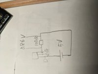
I have tried with 5v battery,100ohm resistor to test Idss.
Tester show 0.86v between 100ohm so it means 10ma x0.86 Idss=8.6ma?
I am reading from diyaudio store information.
https://diyaudiostore.com/pages/jfet-matching-information
Sorry for noob question and some English understanding problem.
I have tried with 5v battery,100ohm resistor to test Idss.
Tester show 0.86v between 100ohm so it means 10ma x0.86 Idss=8.6ma?
I am reading from diyaudio store information.
https://diyaudiostore.com/pages/jfet-matching-information
Sorry for noob question and some English understanding problem.
Attachments
Means I=V/R i.e. 0.86V/100Ω=0.0086A=8.6mA that's correct. And in normal range for PF5102. If your power source was higher like a 9V battery it might have shown a bit more but it does not matter for matching as long as you measure all units with the same power source.

Read somewhere but forgot: is it possible to get 3.8V from UltraBib, which parts must be changed?
So it is a bit unpredictable. It will be used in analog section of R2R DAC. What will be best option:
- use Reflektor-D
- use UltraBib 5v + opa365 3.8V
- use modifiered UltraBib 3.8v (not big diff with 5V): IRL530 and remove one red LED
Unpredictable in a way it will lose enough OLG from its normal spec and will also be easier to make oscillate. Because J3 will operate in a tiny DC voltage bracket. Making R8 5.6k could give some OLG back. C3 should be Low ESR. If easy to test you may give it a try. If no good result IRL530 also works in higher voltage range all the same, so not wasted.
Option two sounds like a proven wise scheme i.e. 5V shunt pre-reg + final low noise LDO closely located on R2R pcb. What is opa365 3.8V plan? Maybe LT3045?
Option two sounds like a proven wise scheme i.e. 5V shunt pre-reg + final low noise LDO closely located on R2R pcb. What is opa365 3.8V plan? Maybe LT3045?
OPA365 already set in Soekris dam2941, good opamp. Besides LT3045 a bit costly.What is opa365 3.8V plan? Maybe LT3045?
Good, thank you for advise, so will buy extra pats: get IRL530 (instead of IRF530), and both R8 270 and 5.6K. But how to test stability: by oscillograph (I have 150MHz), or by extra heat, or by sound, or something else?
you tested it and also without one LED and changed IRF530 -> IRL530, R8 5.6K?BiB can go to 3.8V
I tested following the Salas guide, using BJT output.
BiB guide rev.2 "voltage reference area for 2.5-5.5V Vout BJT output reg. 1 red 1.9V LED, 1K trimmer. Other parts jumper."
BiB guide rev.2 "voltage reference area for 2.5-5.5V Vout BJT output reg. 1 red 1.9V LED, 1K trimmer. Other parts jumper."
ough, this is BiB 1.1 not UltraBib 1.3I tested following the Salas guide, using BJT output.
BiB guide rev.2 "voltage reference area for 2.5-5.5V Vout BJT output reg. 1 red 1.9V LED, 1K trimmer. Other parts jumper."
Thats bib 1.1
Rf makes little EMI RC filter with main reservoir C1. Also offers a handy break point in the circuit if to connect L (choke) for LC instead.
Stability you can test by oscilloscope. Use AC coupling at say 10-20mV vertical. Then switch the horizontal knob between 100uS to 1uS. Should show a straight line when doing well. Even if bit noisy depending on probe's ground length, common mode interference etc. If some sinewave or sawtooth reminiscent AC waveform is discovered that's sure oscillation. Usually HF. Hundreds of kHz or few MHZ. Such a bug can also have many mV or even few V height. If it passes that test OK then by sound you judge subjectively. Better perform any test on dummy load first to safely confirm it generally functions good giving proper DC value etc. then repeat them when connected to the real application.Good, thank you for advise, so will buy extra pats: get IRL530 (instead of IRF530), and both R8 270 and 5.6K. But how to test stability: by oscillograph (I have 150MHz), or by extra heat, or by sound, or something else?
In this schematic and PCB boards I do not see any fuse. Is it necessary to use fuse? Salas L-adapter has fuse and thats why I thought why this schematic do not have it.
Hell, just fish for if anyone has a couple of the boards/kits that they would like to sell on? I would like to try them with a DCG3 pre-amp.
Ta.
Ta.
I've sent you a PM, but may be I've misread your post, sorry. In any case, I have one set of positive/negative regulator boards/kits, in case anyone needs it.
I’ve finally got mine wired up and connected to my BA-3 preamp. Fired it up via variac but the led’s remain out and D3/4 on the negative board and D1/2 on the positive get scorching hot (with maybe a little smoke, not sure). 5R resistor for R1 based on the load from the BA-3. No apparent shorts or anything. Any thoughts?
- Home
- Amplifiers
- Power Supplies
- Salas SSLV1.3 UltraBiB shunt regulator