I've been wanting to build this amp that John Stewart shared with me a while back, and finally found (what I hope) are going to be some good output transformers. Antek has these MP-15W50 15W Output Transformer that are close to fitting the bill, and won't break the bank. If the amp serves me well, of course, I can buy more expensive iron later if I feel I need it.
The design calls for a 4300K 43% UL tapped transformer to provide bootstrapping to the drivers to help overcome the trouble of massive drive signal needed by very low mu 6080 or 6AS7. There is also a way to do this without a UL transformer by adding a couple of extra resistors, which I have procured, but I'd like to do this with the UL transformer to save on the AC losses of using the resistors to provide bootstrapping. I'll post the schematic in a bit, it's something that jhstewart9 published in glass audio many years ago, and has graciously shared here too.
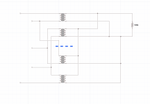
Because I'm a little bit cheap, and a whole lot curious, I also want to get a set of 50VA power toroids from antek to try as output transformers, as some have had success with power toroids as output transformers. Using two transformers, and putting all of the primaries in series will give 480V CT, with two 50% taps for UL/bootstrapping. The plan at the moment is to use transformers with two primaries and two secondaries to get somewhere around 4-6K into 4 ohms. I'm going with 4 ohms on the outputs, since the current speakers I'm using the most are nominal 4 ohms, and It's easier to add some windings to a toroid to get an 8 ohm tap, than it is to tear apart the insulation and remove windings. User kodabmx has reported having good luck using one primary from each transformer in series on each half of the center tap, in order to cross couple them, and reduce interwinding capacitance problems. I'm doing the maths as follows. Please correct me if I'm wrong!
Using the 115V/6V transformer AS-0506, they have a data sheet that shows the unloaded secondary voltage as 6.3V with 120V in. From there I calculate a turns ratio of about 38:1 (using 480V into 12V.6V), or impedance of 5800:4. This gives better distortion figures for most of the range, and may still net me close to the 12.5W out of clean power that John says he got from using a single 6080 with the hammond Iron. Using the 7V transformer I get about 4400:4
a pair of AN-0206 is even less expensive at $12, and two of those together weigh in about the same as the purpose wound 15W output transformer antek makes. The downside is the primaries are only good for about 100mA DC, so I may be on the verge of pushing them a little too hard. Only one way to find out!
The "upgrade" circuit uses two 6080 in parallel, which seems wise, IMHO not just for the extra headroom, but also since it will likely be easier to find two semi-matched tubes, when the two halves are paralleled. I've not tried checking any of these tubes in my pile to see if they are matched close enough or not, but others report that it is not too promising. Using AS-0509, I get 480 into 18.8 for the unloaded voltage and a turns ratio of 25.53:1, and impedance ratio of about 2610:4, which ought to be close enough for triodes 🙂 AS-1209 is the 100VA version, if this one proves to be inadequate.
Target operating point of the design is 250V with 50ma of plate current, or 250v with 100mA for the version with parallel tubes. I have three regulated supplies to run this from for construction and experimentation, and will worry about building the power supply once I've got working circuits. I've got some ideas about lowering the plate voltage a touch to help reduce distortion at the expense of output power. 210V at 60mA with 10W looks a little nicer, but I'll have to build to know! The load line simulator/calculator can only tell me so much without real world trials. The only issue is whether the output transformers will get unhappy with the extra bias current.
The design calls for a 4300K 43% UL tapped transformer to provide bootstrapping to the drivers to help overcome the trouble of massive drive signal needed by very low mu 6080 or 6AS7. There is also a way to do this without a UL transformer by adding a couple of extra resistors, which I have procured, but I'd like to do this with the UL transformer to save on the AC losses of using the resistors to provide bootstrapping. I'll post the schematic in a bit, it's something that jhstewart9 published in glass audio many years ago, and has graciously shared here too.
Because I'm a little bit cheap, and a whole lot curious, I also want to get a set of 50VA power toroids from antek to try as output transformers, as some have had success with power toroids as output transformers. Using two transformers, and putting all of the primaries in series will give 480V CT, with two 50% taps for UL/bootstrapping. The plan at the moment is to use transformers with two primaries and two secondaries to get somewhere around 4-6K into 4 ohms. I'm going with 4 ohms on the outputs, since the current speakers I'm using the most are nominal 4 ohms, and It's easier to add some windings to a toroid to get an 8 ohm tap, than it is to tear apart the insulation and remove windings. User kodabmx has reported having good luck using one primary from each transformer in series on each half of the center tap, in order to cross couple them, and reduce interwinding capacitance problems. I'm doing the maths as follows. Please correct me if I'm wrong!
Using the 115V/6V transformer AS-0506, they have a data sheet that shows the unloaded secondary voltage as 6.3V with 120V in. From there I calculate a turns ratio of about 38:1 (using 480V into 12V.6V), or impedance of 5800:4. This gives better distortion figures for most of the range, and may still net me close to the 12.5W out of clean power that John says he got from using a single 6080 with the hammond Iron. Using the 7V transformer I get about 4400:4
a pair of AN-0206 is even less expensive at $12, and two of those together weigh in about the same as the purpose wound 15W output transformer antek makes. The downside is the primaries are only good for about 100mA DC, so I may be on the verge of pushing them a little too hard. Only one way to find out!
The "upgrade" circuit uses two 6080 in parallel, which seems wise, IMHO not just for the extra headroom, but also since it will likely be easier to find two semi-matched tubes, when the two halves are paralleled. I've not tried checking any of these tubes in my pile to see if they are matched close enough or not, but others report that it is not too promising. Using AS-0509, I get 480 into 18.8 for the unloaded voltage and a turns ratio of 25.53:1, and impedance ratio of about 2610:4, which ought to be close enough for triodes 🙂 AS-1209 is the 100VA version, if this one proves to be inadequate.
Target operating point of the design is 250V with 50ma of plate current, or 250v with 100mA for the version with parallel tubes. I have three regulated supplies to run this from for construction and experimentation, and will worry about building the power supply once I've got working circuits. I've got some ideas about lowering the plate voltage a touch to help reduce distortion at the expense of output power. 210V at 60mA with 10W looks a little nicer, but I'll have to build to know! The load line simulator/calculator can only tell me so much without real world trials. The only issue is whether the output transformers will get unhappy with the extra bias current.
One thing that I'd like to experiment with is using partial fixed bias. These tubes are apparently unstable using fixed bias, and it says not to do it in the tube manuals. for the 6336, it says if using fixed bias that one should have minimum of 10% of the bias from cathode bias. I have the giant resistors needed to do this according to the schematic, but would like to try with 10-25% and see what happens.
I am planning also, while waiting on transformers, to draw out the schematic myself, which has always helped in the past with understanding what is happening in a given circuit. One thing I've been wondering about is whether there's a way around the -150V supply, but it seems unavoidable given the the plate voltage on V2A and V2B is coming from the same source as the output tubes through the UL taps on the output transformer.
I am planning also, while waiting on transformers, to draw out the schematic myself, which has always helped in the past with understanding what is happening in a given circuit. One thing I've been wondering about is whether there's a way around the -150V supply, but it seems unavoidable given the the plate voltage on V2A and V2B is coming from the same source as the output tubes through the UL taps on the output transformer.
If you do go to parallel, use a separate resistor for each cathode...will balance better, makes it easy to compare currents. Of course you'll only want 280V B+ with mostly fixed bias, but still need 440V for the driver. Might be better to use a pot between -10V and +10V to one grid, keeping cathode bias.

I've gotta go digging and find where you found that old post, Tom! I went through lots of thinking about this a while back, then right as I was getting somewhere, I got distracted by job change, and life and all the rest! I was digging in my attic for some other tubes a few weeks ago, and found out I have many more 6as7 than I had previously realized. Finally have the time and resources to start building! 🙂
I found my spice models that I made 4 years ago, and have been working on refining them. Now that I've figured out how to model transformers in there again, I can maybe confirm if my numbers for the mains transformers are kind of correct... Though it means that I need to not stuff up the numbers I'm feeding to the spice model! I started with some ugly distortion, and couldn't figure out where it was coming from. One of the inductors that made up the transformer had the wrong value typed in. That will do it!
Previously, I only modeled this without the feedback circuit. Time to add that, as when the P out gets up to 20W or so, the waves start looking ugly. (this is with the parallel pp "big" version). Also just realized that I've got the impedance ratio in there for the basic PP version, and need to adjust that too.
Well, thanks for the weird mixup! I found some other interesting things while trying to see if I had said that here or elsewhere in the past! 🙂Don't know how that showed up as a quote... I wrote it!
It looks like part of my issue with ugly outputs on the spice model was overloading it using 1V in, instead of the specified .63V in. much better looking.
I've now got the feedback implemented, but spice doesn't like. "Analysis: Time step too small" "trouble with node "u1:gg". U1 is one of the 6080 triodes... I got some really ugly square waves at first, then realized I forgot to ground the output winding/load. I've got a relatively primitive version of spice that I'm using. The macintosh version, at least the one that I downloaded seems to not have much of the interface that the windows version has, so I need to learn a little more how to type things in manually to fix, most likely.
I've now got the feedback implemented, but spice doesn't like. "Analysis: Time step too small" "trouble with node "u1:gg". U1 is one of the 6080 triodes... I got some really ugly square waves at first, then realized I forgot to ground the output winding/load. I've got a relatively primitive version of spice that I'm using. The macintosh version, at least the one that I downloaded seems to not have much of the interface that the windows version has, so I need to learn a little more how to type things in manually to fix, most likely.
I should be able to do away with the negative supply (or at least much of it), if I do away with most of the cathode bias, no? looks like a good bit of it is involved in biasing the 6sn7 drivers?
Spice is nice, when it works! hopefully I will get it figured out a bit better quickly, and be able to make changes there before trying to implement them in real life and blowing up tubes.
Spice is nice, when it works! hopefully I will get it figured out a bit better quickly, and be able to make changes there before trying to implement them in real life and blowing up tubes.
I found some transformer models in one of the spice threads, and they have made the model work correctly now, more or less. I'm using a model of a hammond 1640N, which is what john used for the lower power amp. I've got PP parallel, and using 4ohms on the 8 ohm tap, which gives the equivalent of the special transformer he had wound with half the primary impedance. the 1640 has 4/8/16 ohm taps, so can still handle 4 and 8 ohm speakers if wired that way. the little bit of feedback works wonders to clean up the signal in the model. I'm getting ~25W rms out with third harmonic about 1% in the model. Not sure I've got the feedback quite right, I might need to put it on the 16Ω tap, since I'm using that as the 8Ω tap.
with the feedback on the correct tap, the amp model behaves mostly like described in the article John sent to me. Very neat. The main difference is the actual magnitude of the input voltage to get a certain signal out, but it's well within reasonable tolerances.
One thing I'm curious about is the signal voltages measured at the plates of the input/phase splitter stage, while no feedback is applied. They are not equal, despite all of the components being "ideal" and equally sized. Is this a natural phenomenon with this type of phase splitter? This is a long tail pair, correct? The amp that I've messed around with the most in real life has a concertina type phase splitter with voltage amplifier pentode ahead of it. I was going to try modeling that type of phase splitter to see what the difference is, and whether it too has different magnitudes of output. The disadvantage I saw regarding the concertina phase splitter, is worse overload behavior. When I overload the model as it is designed with LTP, the driver stage clips hard, while the input signal is totally fine still. Part of what I'm trying to learn as I get to building this amp, is why a person chooses one design type over another. Slowly getting a grasp of how spice works has been very helpful in this regard, and probably will save me blowing up some tubes 🙂

One thing I'm curious about is the signal voltages measured at the plates of the input/phase splitter stage, while no feedback is applied. They are not equal, despite all of the components being "ideal" and equally sized. Is this a natural phenomenon with this type of phase splitter? This is a long tail pair, correct? The amp that I've messed around with the most in real life has a concertina type phase splitter with voltage amplifier pentode ahead of it. I was going to try modeling that type of phase splitter to see what the difference is, and whether it too has different magnitudes of output. The disadvantage I saw regarding the concertina phase splitter, is worse overload behavior. When I overload the model as it is designed with LTP, the driver stage clips hard, while the input signal is totally fine still. Part of what I'm trying to learn as I get to building this amp, is why a person chooses one design type over another. Slowly getting a grasp of how spice works has been very helpful in this regard, and probably will save me blowing up some tubes 🙂
I modeled the amp in John's alternative design, using a standard center tapped output transformer, and 4 27K resistors laid out across the primary, with B+ going to the middle of the string, and the nodes of the two pairs either side of B+ acting as virtual UL taps. At first, disappointed by 25% loss in output power, I realized that these extra resistors were going to be dropping B+ available to the drivers. I adjusted the common cathode resistor of the driver stage until the plate voltages on the drivers were the same as with the UL transformer, and then have only a 12% loss of power at the output, but I've got double the cathode current, from 10.3 ma to 20.5ma. Perhaps adding two more capacitors to block DC from the bootstrapping to the plates of the drivers, and then connecting B+ directly to the plates is a better option?
Doing FFT of the voltage across the output load resistor (speaker load for model), there is only a 1db increase in 3rd harmonic distortion level for the same input, with 12% loss in output power. not so bad after all. This all without feedback connected. I think I will see with feedback, the performance cost is not so high for the virtual UL tap resistor divider design. Perhaps with some more tweaking of things, I can minimize the losses even more, and save needing to buy UL output transformers after all.
Next up is to test all of this with feedback applied and see what happens. If it goes well, I have a set of ordinary PP transformers that will work for both 4K input impedance, and 2K, I think, so could try with single or parallel outputs.
With the same modest amount of feedback applied in both cases, and the cathode resistor of the driver tubes adjusted to give the same plate voltage on the drivers, it's the same situation, with double the cathode current on the drivers in the version with virtual UL taps. with 3V signal in, power out is approximately the same in both versions (about 14.5W rms), with 3rd harmonic -45dB vs -47.5dB for the original version. power difference is about 4%.
A little more study, and I remembered that four 27K resistors would make the equivalent of 50% UL taps, vs the 40% on the hammond transformer. leaving the rest of the circuit identical and changing that string to 27K-40K-40K-27K restores the power out performance to nearly identical to the UL tapped transformer version (actually slightly higher now), at least with this input level. there is, however, a 3db penalty for 3rd harmonic distortion. With some other tweaks to the driver operating point, perhaps this can be evened out a bit too.
Adding 10K resistors in line with the driver plate into the bootstrapping network adds a little power out,equalizes the operating point of the drivers to the original circuit. This along with increasing feedback a tad (resistor changed from 4.7K to 4.4K) results in equal performance to the UL transformer in both power and distortion numbers with identical input voltage. Not bad. Thank you, John Stewart! Perhaps no UL transformer needed after all!
Attached is current simulation schematic. Transformer model is hammond 1650N, with 4Ω on 8Ω tap to get appropriate impedance ratio. I'm going to try some ideas with the input section, and hopefully this weekend will get to building something!

Attached is current simulation schematic. Transformer model is hammond 1650N, with 4Ω on 8Ω tap to get appropriate impedance ratio. I'm going to try some ideas with the input section, and hopefully this weekend will get to building something!
More recently I changed the 6080 cathode resistors to a version that can be attached to a heat sink. It heat sinks to the aluminum chassis but external Wakefield sinks would help a lot. Something to consider if the amp will be run continuously. Mine is strictly experimental.
On the bench now for the last couple of weeks. When I get a break I've run more performance checks. I'll post later.
On the bench now for the last couple of weeks. When I get a break I've run more performance checks. I'll post later.
I'm planning to mount them above chassis, but also want to try to see if I can make it work with partial fixed bias to cut the heat down a little bit at least.
I did some experiments last night in spice to see what the difference was with bootstrapping and without. With no global feedback applied, the amp without bootstrapping peters out at about 20w. With bootstrapping, you get an extra 5 watts out, at least before really serious distortion sets in, and the amp refuses to clip hard for much longer. The no bootstrap situation, it gets to a point where it will make less power the more you put in. The bootstrapped version it just makes more power, even when the distortion gets above an acceptable level. I compared the distortion charchteristics at various power levels, and the no bootstrap circuit had slightly better levels for third harmonic throughout until clipping, but higher order harmonics weren’t as suppressed as they were in the version with bootstrapping to the drivers. Overall THD levels looked about the same, just slightly different makeup.
Tonight a spent a lot of time trying to figure out how to use partial fixed bias on the output section. you run up against a problem where the lower you have the bias, the less voltage is available for the driver stage. theres a certain point, where I couldn’t get the driver to make enouh voltage swing. I ended up settling on about 40% cathode bias, and 60% adjustable fixed bias from the negative 150v source designed into the power supply. This gives roughly 48v of cathode bias from the total of 125v bias needed to get any power out of the 6080 tubes. B+ is A modest 300V. This is still problematic for the drivers, as they’re being asked to swing about 200V at 25w rms output. I fiddled about for hours, and finally got to a point where I had enough drive. It’s not pretty, but amazingly it looks promising. The 6sn7’s have roughly the same bias voltage, but a fair bit more current at idle. They’re burning 2W instead of the roughly 1W in the original design. I had to reduce the value of the resistors coming from the UL taps to the drivers down to 8K from 27K In order to get enough voltage. With the current bumped up, the 6sn7’s just barely have enough oomph.
I learned in all of this, that the drivers are basically going to define the sound of this circuit, in terms of the harmonic content. I’ve got a fair bit of 2h distorition coming off of the driver stage, and somehow this is finding its way to the output. Interestingly, distortion overall is lower than any other version of the amp that I have modeled, and it falls off beautifully with 2nd dominating, third less, 4th even lower, and so on. I’ve got to see how it works if I do this using the voltage divider method, instead of with a UL transformer, but I also need to sleep at some point 😉
i still have to re-work the input stage a bit more to my liking. I want to see if I can make it work with a simple concertina phase splitter, but I’m not sure if there is enough drive to be had from one of those to swing the driver grids without extra distortion. My first attempt using a 6sl7 for this job didn’t work out well, but I’m getting a little better at figuring out what might work, so will probably try again, now that i have the drivers and outputs sorted better. I got ahold of some spice models for the 6U8, and have an existing amp and schematic that I can model now to see how that family of tubes might work.
Last edited:
- Home
- Amplifiers
- Tubes / Valves
- A different kind of triode amplifier...