A friend of mine had put to my attention this project a while ago. I had read the thread and found that it was an interesting design. So, time had come to give it a try.
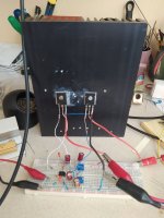
To make things easier, and since this is a quite simple circuit, I decided to build it on a breadboard, for the sake of simplicity. In just less than an hour, I had built one channel and powered it from my lab regulated PS. The problem I encounter is that, whatever I tried, the P channel always draws 200 mA more current than the N channel. Increasing the current on the + side, increases accordingly the current on the - side and vice versa.
Checking the amp on the oscilloscope, I didn't notice any flaws: the signal is perfectly symmetrical all the way to clipping.
Any suggestions here?
Regards,
Evangelos
Attachments
This might have to do with differences in FETs because they were not matched. Did you measure them or attempt to match them?
Try this method:
Even one of these $10 component testers is better than nothing:

Try this method:
After building a couple of multi-output device MOSFET amps, I noticed that the current draw between the devices can vary wildly sometimes. Good thing for source resistors to allow load-balancing. I knew this was happening because I did not have Vgs matched resistors. So how to match them - I looked around for awhile on these threads but nothing jumped out as an easy to do HOWTO guide.
So here is the guide for dummies like me - I will call these threads the "Easy Peasy" (TM) threads. You may have seen the similar titled Juma's Easy Peasy Cap Multiplier thread. So I...
So here is the guide for dummies like me - I will call these threads the "Easy Peasy" (TM) threads. You may have seen the similar titled Juma's Easy Peasy Cap Multiplier thread. So I...
- xrk971
- Replies: 39
- Forum: Solid State

Even one of these $10 component testers is better than nothing:
Last edited:
As far as I know, never N and P channel MOSFETs cannot be matched. Usually, the P channel has a higher Vgs than the N channel.
And, yes, I have measured them. I have 4 pairs of Exicon lateral FETs. All N channel FETs have a Vgs of ca. 1.4 V, while P channel FETs have a Vgs of ca. 1.9 V.
Adding a source resistor to the P MOSFET would negate the square law transfer characteristic of the laterals.
juma states in his presentation in the first post of this thread:
"We use Laterals without source resistors so we can exploit their square law transfer characteristic and the exact bias current value is not that important but you can play with it."
I'm trying to interpret this sentence regarding the bias current value. Does he imply that a difference in bias current is acceptable?
BTW, what is this tester?Even one of these $10 component testers is better than nothing: