After building a couple of multi-output device MOSFET amps, I noticed that the current draw between the devices can vary wildly sometimes. Good thing for source resistors to allow load-balancing. I knew this was happening because I did not have Vgs matched resistors. So how to match them - I looked around for awhile on these threads but nothing jumped out as an easy to do HOWTO guide.
So here is the guide for dummies like me - I will call these threads the "Easy Peasy" (TM) threads. You may have seen the similar titled Juma's Easy Peasy Cap Multiplier thread. So I have been looking for an easy to do and clearly detailed way to measure Vgs on my MOSFETs for a while. Maybe it is so obvious to folks on this forum but for me, it took a tip from member Idefixes to look at Nelson Pass' article here:
https://www.passdiy.com/project/articles/matching-devices
Which basically says use this easy peasy circuit:
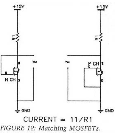
If you happen to have a solderless breadboard, a 2.2k resistor, a DVM, and a 15v power supply, you are all set. I happened to receive these little XL6009 DC-DC boost modules in the mail today. Slick little buggers that take almost any DC input and step up and regulate it nicely (supposedly good for 4A but the Schottky diode on board is rated 1A). Anyhow, with a trimpot I could dial in anything from 12V to 35V with 12V input and 15 to 30mV ripple depending on setting.
Here are the units, you can get them from anywhere:
https://www.amazon.com/gp/product/B00J1X4XXM/

And then I have a couple of these solderless breadboards for $4 (the bundle of hard wire tipped jumpers alone is woth the price):
https://www.aliexpress.com/item/3-3...less-Prototype-Bread-board-kit/749581037.html

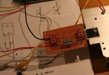
So anyhow, I proceeded to wire it up just like the diagram above and went to town measuring the Vgs of my MOSFETs at a current of 5mA.
Adjust your power supply for 15.0v, make sure your resistor is a 1% 2k2 metal thin film (1/4w will do). I added some gate protection to the circuit to avoid blowing the gates with a bad hookup or a transient using a 12v zener and 1N4148 in series from gate to ground.
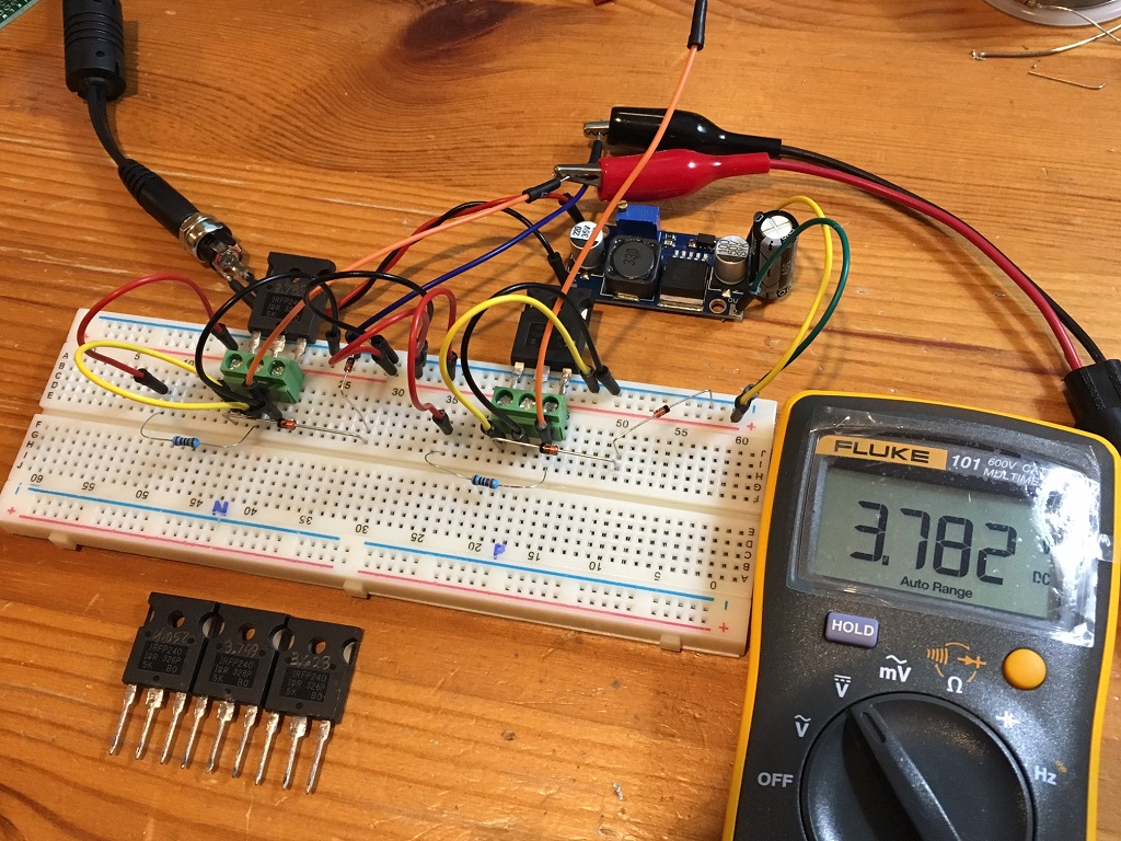
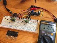
Next step is how to attach the big fat pins from an IRFP240/9240 (TO-247AC) packages? Well, it turns out that a 3-pin PCB mount screw terminal block holds the pins securely and precisely without damage (the screws actuate a lever that clamps the pins so no marring or damage to the pins occurs). Of course, a TO-220 will push right into the breadboard and that's what I did for my 2SK2013 and 2SJ313's.
So here it is in action (N channel on left side and P channel on right side):
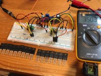
I then added jumpers to do TO-220's here. These SK2013's and 2SJ313's have some spread but not too bad and certainly, they are proven to be functional in use as an amp and show reasonable Vgs:

It made quick work of measuring Vgs - which I just wrote onto the satin finish of the MOSFET body with a pencil. A large batch of the IRFP9240 that I got from Aliexpress for $1ea were actually matched within 0.01v for 5 of them Anyhow, I am real glad I made this jig, it's going to be really useful and well used in the future. I hope you find this helpful.
So here is the guide for dummies like me - I will call these threads the "Easy Peasy" (TM) threads. You may have seen the similar titled Juma's Easy Peasy Cap Multiplier thread. So I have been looking for an easy to do and clearly detailed way to measure Vgs on my MOSFETs for a while. Maybe it is so obvious to folks on this forum but for me, it took a tip from member Idefixes to look at Nelson Pass' article here:
https://www.passdiy.com/project/articles/matching-devices
Which basically says use this easy peasy circuit:
If you happen to have a solderless breadboard, a 2.2k resistor, a DVM, and a 15v power supply, you are all set. I happened to receive these little XL6009 DC-DC boost modules in the mail today. Slick little buggers that take almost any DC input and step up and regulate it nicely (supposedly good for 4A but the Schottky diode on board is rated 1A). Anyhow, with a trimpot I could dial in anything from 12V to 35V with 12V input and 15 to 30mV ripple depending on setting.
Here are the units, you can get them from anywhere:
https://www.amazon.com/gp/product/B00J1X4XXM/
And then I have a couple of these solderless breadboards for $4 (the bundle of hard wire tipped jumpers alone is woth the price):
https://www.aliexpress.com/item/3-3...less-Prototype-Bread-board-kit/749581037.html
So anyhow, I proceeded to wire it up just like the diagram above and went to town measuring the Vgs of my MOSFETs at a current of 5mA.
Adjust your power supply for 15.0v, make sure your resistor is a 1% 2k2 metal thin film (1/4w will do). I added some gate protection to the circuit to avoid blowing the gates with a bad hookup or a transient using a 12v zener and 1N4148 in series from gate to ground.
Next step is how to attach the big fat pins from an IRFP240/9240 (TO-247AC) packages? Well, it turns out that a 3-pin PCB mount screw terminal block holds the pins securely and precisely without damage (the screws actuate a lever that clamps the pins so no marring or damage to the pins occurs). Of course, a TO-220 will push right into the breadboard and that's what I did for my 2SK2013 and 2SJ313's.
So here it is in action (N channel on left side and P channel on right side):
I then added jumpers to do TO-220's here. These SK2013's and 2SJ313's have some spread but not too bad and certainly, they are proven to be functional in use as an amp and show reasonable Vgs:
It made quick work of measuring Vgs - which I just wrote onto the satin finish of the MOSFET body with a pencil. A large batch of the IRFP9240 that I got from Aliexpress for $1ea were actually matched within 0.01v for 5 of them Anyhow, I am real glad I made this jig, it's going to be really useful and well used in the future. I hope you find this helpful.
Attachments
Last edited:

@ XRK971
Thx for knowlege share i appreciate this useful thread.


ps. non temperature controled heat sinks used for DUT ?
You are welcome - glad you find it helpful.
The Vgs test is at 5mA so there is no heat generated really. There is a high current test that Mr Pass mentions in the above article and that will require a heatsink.
slight error.
The Vgs of the D to S coupled mosFET subtracts from the supply voltage to leave the remainder across the resistor.
If the Vgs is not exactly the same for each device then you will find that Vrd varies.
The effect is that your jig is not testing Vgs at a fixed 5mA. That 5mA varies.
You can change the resistor (Rd) to a CCS set to 5mA + a monitoring resistor to check whether the CCS holds a steady fixed current for each device.
Member
Joined 2009
Paid Member
I used essentially the same thing: http://www.diyaudio.com/forums/soli...lifier-based-greg-ball-ska-2.html#post3616316
I used a circuit where both p and n type devices have the gate tied to the drain and to ground.
I used a circuit where both p and n type devices have the gate tied to the drain and to ground.
Attachments
Last edited:
slight error.
The Vgs of the D to S coupled mosFET subtracts from the supply voltage to leave the remainder across the resistor.
If the Vgs is not exactly the same for each device then you will find that Vrd varies.
The effect is that your jig is not testing Vgs at a fixed 5mA. That 5mA varies.
You can change the resistor (Rd) to a CCS set to 5mA + a monitoring resistor to check whether the CCS holds a steady fixed current for each device.
Thanks for noticing that. I think it might be simpler to put a pot there and adjust until voltage across the sensing resistor shows 5mA - would have to manually be done each time whereas a CCS would be automatic. Maybe a fixed current source diode like a J511 (4.7mA) or a JFET can work here?
I used essentially the same thing: http://www.diyaudio.com/forums/soli...lifier-based-greg-ball-ska-2.html#post3616316
I used a circuit where both p and n type devices have the gate tied to the drain and to ground.
Oh, I missed that - you used the 3 pin screw block terminal too!
")
So here is the guide for dummies like me - I will call these threads the "Easy Peasy" (TM) threads.
Good luck trying to trade-mark "Easy Peasy" -- it was snatched in February 2016.
I use my lab power supply and adjust the lab output voltage to trim the fixed test current.Thanks for noticing that. I think it might be simpler to put a pot there and adjust until voltage across the sensing resistor shows 5mA - would have to manually be done each time whereas a CCS would be automatic. Maybe a fixed current source diode like a J511 (4.7mA) or a JFET can work here?
Alternatively I can use the current limiter, leave that set to a fixed value. But this is only effective at much higher output currents.
I built a couple of 1943 and 5200 (on 10C/W sinks) based BJT 2 transistor current sources.
These can have presettable resistors for a range of fixed test currents. But The CCS action is affected by temperature. And temperatures change repeatedly as DUTs are plugged and unplugged !
Last edited:
I use my lab power supply and adjust the lab output voltage to trim the fixed test current.
Alternatively I can use the current limiter leave that set to a fixed value. But this is effective at much higher output currents.
I bulit a couple of 1943 or 5200 based BJT 2 transistor current sources.
These can have presettable resistors for a range of fixed test currents. But The CCS action is affected by temperature. And temepratures changes repeatedly as DUTs are plugged and unplugged !
I almost forgot that I have a "lab" power supply now with a trimpot adjustable voltage. I should build a small box with a real pot knob.
To build a free-of-temperature-drift constant current source that outputs anywhere between 2.5mA and 2.5 amperes, get a low-tempco, 1.0 ohm power resistor like this one: -80ppm / degreeC, rated for 7 watts.
Connect the resistor in the source leg of a power MOSFET, and use that assembly plus an opamp to build a precise VCCS: voltage controlled current source. The opamp guarantees that the voltage across the resistor is V_user_adjusted and so the current is (V_user_adjusted / R). Since R is a very weak function of temperature, so is current. Choosing a 1.0 ohm resistor makes setup and calibration especially easy. V_user_adjusted comes from a temperature-independent reference voltage (LM285-2.5 @ 20 ppm/degC would be quite handy) and a potentiometer.
BTW comparison requires O(N^2) insertions. Individual measurement requires O(N) insertions. And of course the comparison circuitry needs to be matched much, much better than the hoped-for matching of the MOSFETs.
Last edited:
Next thing is how to easily measure Idss on JFETs.
Maybe the JFET test jig that I built (schematic and PCB here) might give you some ideas.
It measures both PJFETs and NJFETs and gives you two pieces of data: (a) Idss @ Vds = Vbattery; (b) Vgsoff @ a couple dozen nanoamperes of Ids. You could change the source resistors R1+R3 to measure Vgsoff at a different current if you prefer.
To build a free-of-temperature-drift constant current source that outputs anywhere between 2.5mA and 2.5 amperes, get a low-tempco, 1.0 ohm power resistor like this one: -80ppm / degreeC, rated for 7 watts.
Connect the resistor in the source leg of a power MOSFET, and use that assembly plus an opamp to build a precise VCCS: voltage controlled current source. The opamp guarantees that the voltage across the resistor is V_user_adjusted and so the current is (V_user_adjusted / R). Since R is a very weak function of temperature, so is current. Choosing a 1.0 ohm resistor makes setup and calibration especially easy. V_user_adjusted comes from a temperature-independent reference voltage (LM285-2.5 @ 20 ppm/degC would be quite handy) and a potentiometer.
BTW comparison requires O(N^2) insertions. Individual measurement requires O(N) insertions. And of course the comparison circuitry needs to be matched much, much better than the hoped-for matching of the MOSFETs.
That sounds really nice Mark but sort of defeats the "Easy Peasy" requirement. I also ask if the simple non constant current method is used by Mr Pass, isn't it good enough for matching MOSFETs for typical amp power output stages? Certainly better than what I was doing before (nothing).
It's merely a follow up to other posts which remark that the least complicated, simplest "constant current sources" usually drift quite a bit with temperature. If you don't feel like building a temperature-stable CCS to test and sort your $1 MOSFETs from Aliexpress, you are of course completely free to choose another approach. But in case you are wondering how somebody might do it, there's my answer: low-tempco power resistor + low-tempco reference voltage + potentiometer + negative feedback circuit using opamp and MOSFET.
Does the VCCS opamp require the opamp to be rail to rail input when powered from the same Zero Volts as the CCS?To build a free-of-temperature-drift constant current source that outputs anywhere between 2.5mA and 2.5 amperes, get a low-tempco, 1.0 ohm power resistor like this one: -80ppm / degreeC, rated for 7 watts.
Connect the resistor in the source leg of a power MOSFET, and use that assembly plus an opamp to build a precise VCCS: voltage controlled current source. The opamp guarantees that the voltage across the resistor is V_user_adjusted and so the current is (V_user_adjusted / R). Since R is a very weak function of temperature, so is current. Choosing a 1.0 ohm resistor makes setup and calibration especially easy. V_user_adjusted comes from a temperature-independent reference voltage (LM285-2.5 @ 20 ppm/degC would be quite handy) and a potentiometer.
BTW comparison requires O(N^2) insertions. Individual measurement requires O(N) insertions. And of course the comparison circuitry needs to be matched much, much better than the hoped-for matching of the MOSFETs.
Can an ordinary BJT input with pnp for the LTP perform when the Vee is at the same Zero Volts as the CCS.
Is there any advantage or disadvantage in using a FET input opamp?
Last edited:
- Home
- Amplifiers
- Solid State
- Nelson Pass' Easy Peasy MOSFET Vgs Measurement