
Do you have the B1 oscillator in the UPL? I wonder what you get from that with 2VRMS / 1KHz? My UPVs vary between -112 to -115dbV (they average -112 to -114, but one of them will hit -115 if the wind is blowing in the right direction). The SYS-2722 can get -115dBV when feeding the UPV.
The HP339A performance is stellar for such an ancient unit.
The HP339A performance is stellar for such an ancient unit.
Hi thermionic,
the THD and THD+N measurements I took yesterday were from the HP339A generator. Unfortunately my UPL does not have a B1 low distortion oscillator option. This was too expensive for me as a hobby device. The UPL with B1 option still costs over 6,000 euros today. Not to mention the UPV with B1, which costs > 10,000 euros. The DAC oscillator from my UPL delivers about -112dB THD and -105dB THD+N at 1kHz 1-10V RMS. But I can also measure up to -118dB THD+N with my UPL analyzer (with an external low distortion oscillator connected, if I go up to just over 3V RMS input voltage, i.e. manually set the input sensitivity to 3V). For example, I measured the oscillators I developed myself. In fact, they deliver up to 4 dB better THD+N, i.e. around -122dB (at 1KHz-3V 22kHz BW) see also my post on page 506 in this thread, where I had an oscillator of mine measured with the APX555. If you measure the UPV B1 generator with an APX555, it could well be that it also achieves a THD+N of perhaps -116 to-118dB.
Best regards
Helmut Sell
My experience with the UPV-B1 is that the oscillator averages 1.5-2dB worse THD+N combined than the SYS-2722. My worse UPV-B1 struggles to get -112dB THD+N, but the best can achieve -115dB (the other two get around -113dB - which is what I've always expected from a UPV-B1). The SYS-2722 gets a solid -115dB THD+N, but can nudge -116dB on the right day. I get the impression that the input section on the UPV is capable of better THD+N than the B1 oscillator. I also get the impression that THD+N specs for the UPL and UPV are pretty much the same. I suspect that they focused on features when the UPV came out and didn't feel the need to get into a race for THD+N. If R+S ever released a new AA I would have G.A.S. I don't get G.A.S over the 555 TBH. Too many add-on expenses. It seems like a wallet-gouging activity to me, great though it is.
NB - there is definitely a little LF noise inherent to the UPV... I have always wondered if putting the PSUs in an external enclosure would do anything... (there are 2: a large linear board, and a SMPS)
NB - there is definitely a little LF noise inherent to the UPV... I have always wondered if putting the PSUs in an external enclosure would do anything... (there are 2: a large linear board, and a SMPS)
There must be more exact reason then just 'age'. It's interesting what makes it worse than it can be with nowadays parts.The original HP339A obviously cannot achieve this, simply because of its age of almost 50 years.
The reason is more the time it was designed and the components available. That's "age" in this case. We've learned more ad can design better oscillators today. However, what HP did is truly top of class given it was mass produced as well. All this 50 years ago approx.
I have a couple 339A, and 33xA THD meters plus 65xA oscillator models also. Most other brands don't come close.
I have a couple 339A, and 33xA THD meters plus 65xA oscillator models also. Most other brands don't come close.
I have just fired up an HP 339A that does not appear to have ever been opened. Calibration seals are still intact. Pots + switches are noisy, and need a little nursing to give best results. Note that this UPV has the worst digital oscillator of any of our UPVs - they usually get better than this (it seems to give a better THD+N than THD alone, which is a little odd). The B1 oscillator is the optional low-THD option and UPV works nicely in this mode. All measurements are taken via UPV inputs (I haven't bothered testing the inputs on the 339A TBH).
@ 1KHz
THD @ 2VRMS UPV standard oscillator = 105dB
THD @ 2VRMS HP339A = -112.5-113 dB
THD @ 2VRMS UPV-B1 = -118dB
THD+N@ 2VRMS UPV standard oscillator = 106.5dB
THD+N @ 2VRMS HP339A = -111.4 dB
THD @ 2VRMS UPV-B1 = -114dB
@ 20KHz / 2VMRS the 339A gives -103dB THD (80K BW) and -100 THD+N (80K BW)
(in truth is was -99.9 THD+N, but I rounded it down out of respect for a 1977 veteran)
How good will the 339A be with a good service and the modifications described by Helmut? For a 1977 machine to have better THD+N than the UPV's digital oscillator is quite something. I tested it against another UPV and saw that it still beat the digital oscillator by 1-2dB THD+N, so not as much as in the above test - but impressive nevertheless.
I wonder how the 339A's oscillator compares to later HP AAs?
It would seem that my measurements of the 339A mirror Helmut's nicely. I should get some work done and stop geeking around with test gear...
Given it hasn't had any service ...
You may be able to lower noise in the DC regulators and other sections. The pot change also helps.
You may be able to lower noise in the DC regulators and other sections. The pot change also helps.
I need some help with a particular circuit used in the Tektronix SG505.
I'm currently working on a DIY rebuild of the SG505, as a fun project and learning experience.
The generator itself is working according to the specifications as far as I can tell, but the output amplifier is adding significant harmonic distortion. The amplifier uses a JET and the function of it is a mystery for me.
Can somebody out here explain that to me please?
The JFET is a Tek p/n 151-1025-00, originally an SPF3036. The recommended replacement is the 2N4416, and that can be replaced by a J111. I have tried several different JFET's in the circuit, but without significant changes. Even when I take the JFET out of it's socket, there is little change in the FFT.
Here is my blog with the project details: Blog
Here is the SG505 manual: SG505 manual
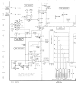
The output amplifier section is on page 63.
Below is a small section of the circuit diagram.
Many thanks in advance!
Paul
I'm currently working on a DIY rebuild of the SG505, as a fun project and learning experience.
The generator itself is working according to the specifications as far as I can tell, but the output amplifier is adding significant harmonic distortion. The amplifier uses a JET and the function of it is a mystery for me.
Can somebody out here explain that to me please?
The JFET is a Tek p/n 151-1025-00, originally an SPF3036. The recommended replacement is the 2N4416, and that can be replaced by a J111. I have tried several different JFET's in the circuit, but without significant changes. Even when I take the JFET out of it's socket, there is little change in the FFT.
Here is my blog with the project details: Blog
Here is the SG505 manual: SG505 manual
The output amplifier section is on page 63.
Below is a small section of the circuit diagram.
Many thanks in advance!
Paul
Attachments
It was mentioned earlier. Q1620 and U1520 form a low distortion composite amplifier as described in the US patent 4296381. A similar arrangement with opamps instead of a JFET was discussed by John D. Yewen in his article "High-precision composite op-amps", Electronics & Wireless World, February 1987.
Last edited:
@Paulwv -- Bob Cordell made a DIY version of the SG505 in a series of 3 articles in Audio Magazine, 1981: https://www.cordellaudio.com/papers/thd_analyzer.pdf
I think that the effect of the feed forward (C1621 and C1622) and FET (Q1620) depend on the internal circuit of the NE5534 used. So is going to depend on who the manufacturer is and the mask variant. It may even need some select on test or selection to work well. It's also going to depend on the FET transconductance when the gate source voltage is close to 0.
Maybe a simpler solution is to use a different operational amplifier such as an OPA1611 or similar?
Maybe a simpler solution is to use a different operational amplifier such as an OPA1611 or similar?


I was not aware of this post by Sam (with good tips) nor the patent. Thank you.It was mentioned earlier. Q1620 and U1520 form a low distortion composite amplifier as described in the US patent 4296381. A similar arrangement with opamps instead of a JFET was discussed by John D. Yewen in his article "High-precision composite op-amps", Electronics & Wireless World, February 1987.
Thank you, that helps.I think that the effect of the feed forward (C1621 and C1622) and FET (Q1620) depend on the internal circuit of the NE5534 used. So is going to depend on who the manufacturer is and the mask variant. It may even need some select on test or selection to work well. It's also going to depend on the FET transconductance when the gate source voltage is close to 0.
Maybe a simpler solution is to use a different operational amplifier such as an OPA1611 or similar?
I doubt however that Tek (Bruce) would build an instrument that would be so much dependent on components. They usually design ( and use conservative specs) so their instruments can be build over many years.
At this moment I want to see how close I can get with the original design, as I said for fun and learning. I first need to have a reference before even attemting to improve things.
Thank you, I have this in my archive for a few decades already. BTW, it's not a DIY version of the SG505, but Bob used it as an inspiration, and did his own excellent design with several improvements.@Paulwv -- Bob Cordell made a DIY version of the SG505 in a series of 3 articles in Audio Magazine, 1981: https://www.cordellaudio.com/papers/thd_analyzer.pdf
Paulwv my explanation of the function of the FET, Q1620 in the Tektronix SG505 output amplifier is:-
To buffer and invert the error signal at the operational amplifier, U1520, inverting input (due to the finite loop gain of the operational amplifier) then AC couple via C1522 this signal to the non-inverting input of the operational amplifier. This increases the error signal between the inverting and non-inverting inputs increasing the loop gain so reducing the distortion.
The input to the non inverting input is attenuated beyond about 1 MHz by the low pass filter formed by the output impedance of the FET amplifier, R1620, and the capacitor C1520 to reduce the loop gain at high frequencies and hopefully prevent instability at high frequencies.
According to the data book that I am looking at (Siliconix Low-Power discretes 1994) the 2N4416 the saturation drain current, IDSS, is between 5 and 15 mA at VDS = 15 V and VGS = 0V).
Under the same conditions the J111 IDSS = 20mA min. The J112 looks to be a better match to the 2N4416 with IDSS = 5 mA min (if available).
Hi PChi,
Thank you for the elaborate explanation. It confirms what we already gathered from LTspice ourselves and the patent that @alexcp provided.
So it seems you are the lucky person that held on to their old data books. 😉 However, this datasheet is available online as well:
https://nl.mouser.com/datasheet/2/676/jfet_2n4416_2n4416a_interfet-2887738.pdf
Your JFET information is interesting. When I looked for suitable replacements for the 151-1025-00/SPF3036, I found a blog post about Tek products where they mentioned the Interfet 2N4416 as an "equivalent" replacement. DigiKey in turn shows the J111 as the replacement for the 2N4416. That's where I got it from.
I have the J112, J113 and tried them without much difference or improvements. I also ordered the J111, and will try that one too.
But I first need to do a better job looking at the harmonic differences, and need to upgrade my Twin-T with improved shielding.
I'm also going to try the Viktor 1KHz oscillator with the SG505 output amp to see what it does. There's something fishy with the way I put this amp together, but I don't know what yet. It seems to work really well, but adds a lot of harmonics to the clean generator.
On this topic, the JFET in the AGC.
I have a Curve Tracer and profiled the 151-1021-00 used in the AGC for suitable replacements. I actually have two of them. It seems that the 2N4391 or the MMBF4391 is not the same but the closest replacement. With it, my SG505 generator circuit is close to the specifications. BTW, Viktor Mickevics also uses that same part in the AGC of his reference oscillators.
And then, there are the write-ups from Dick Moore about his version of the Bob Cordell generator (relative of the SG505 SV design) where he did a lot of testing for the best JFET in the ACG as well.
Dick Moore website
If you're interested, keep an eye on my blog where I detail the DIY rebuild attempts of the SG505.
Regards,
Paul
When substituting Q1620, one thing to watch for is the stability of the composite amp. Since the J111 has a higher transconductance vs. the 2N4416, the bandwidth of the integrator Q1620 R1620 C1520 will be somewhat higher and may be a little too high for the composite. Test the composite on a low amplitude, fast rise square wave. If the overshoot is not aperiodic, try increasing C1520. Also, the amp will work without Q1520 - it will be just a normal inverting opamp.
- Home
- Design & Build
- Equipment & Tools
- Low-distortion Audio-range Oscillator