Member
Joined 2009
Paid Member
Yes, that's what I was suggesting. Only I would not use 100R for the emitter degeneration - I think it's too high and although it nicely smooths out the gain curve of the LTP it robs it of too much gain when used with a simple single transistor voltage amplifier following it. I think in my build I used 10R max but I may have experimented with 4R7 too. Just enough to buy you a little tolerance on the LTP behaviour but still retaining good gain.
I don't want to hijack your post but I would refer you to the schematic I posted here: https://www.diyaudio.com/community/threads/tgm-amplifier.140461/page-18#post-3259963
The value of the capacitor in question is best chosen by ear because it's so instructive to hear the differences and get a feel for the design. Anyhow, with the transistor I used and the layout I used I found that a value around 47pF would be a good starting point. I found that 15pF was too small (sound was not quite right, a little bright or something) and 100pF is too big (sound loses it's magic whatever that means).
In your schematic, I would advise using high quality electrolytic (e.g. Nichicon MUSE or whatever they call their hi end audio range these days) for C4 and C13. The capacitor that filters the power to the LTP (C13) can be interesting to try different values. The bootstrap cap, C4, can be increased to 220uF if a high quality cap is on-hand as it supports lower frequencies better.
The input cap, C6, is usually a high quality film type and needs good space for the higher quality ones. However, many years later I discovered that I got great sound from using a Nichicon Bi-Polar (audio grade) capacitor of around 10uF but this does change the time constant at the input.
It's a great amp to DIY.
Last edited:
All ok...dont see it as hijacking
100 pf only for examle, 100 ohm resistor too...
I will have a look to your schematic...to find the differences..
Thanks
Peter
100 pf only for examle, 100 ohm resistor too...
I will have a look to your schematic...to find the differences..
Thanks
Peter
Hi,
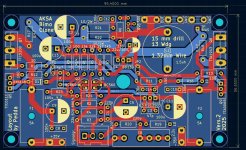
now the AKSA has two emitter resistors. That was no nice work because I dont wanted to change the size of the pcb. Moved a few componets and now it is finished.
@Bigun thanks for your advices.
I think nobody had tried to make a layout from the BIMO schematic until yet...
For the little pf capacitors i always use glimmer CY22-2. For nf i use wima capacitors RM5. Electrolyt muses are very good and i use if i can get with the right diameter.
In the AKSA amp R23/R24 R12/13 R15/R16 the resistors should be 0,1 % or measuring out for identical value....
I uploaded new gerber files with emitter resistors.
It was only a favor to make this pcb, dont know if i ever built one. I have too much own projects..
Greets
Peter
Attachments
Last edited:
Hi Peter
Hi Bigun
nice little amp. its very similar to the JAT EZ amp (actually with darlingtons) which i started with a lot of help.
JAT EZ amp
sorry i am not a specialist but I do not understand why you do not use mandatory things like CCS for the LTP? or a degeneration resistor at Q3 for setting the Dc offset?
@Peter Barth very nice PCB- as always 🙂
kr
chris

Member
Joined 2009
Paid Member
Hey Chris, there's nothing 'mandatory' about circuit elements but you are right that a CCS is best practice for reducing distortion. However, the resistive long tail for the LTP along with other circuit elements are key to the sound of this amplifier (read my TGM thread, I think there's more in there). If you want to go all-out in terms of best practices then I would offer this: https://www.diyaudio.com/community/...-by-rod-elliot-p3a.245619/page-32#post3785052
Hi
i did not read your thread here .What are Jumper 1 +2 for?
i guess it is for let the VAS and OPS not work and measure the LTP and other voltage parameter?
what happend if we use instead of R1 (15k) a CRD? with e.g. 2mA --E202?
CRD with 2mA
kr
chris
i did not read your thread here .What are Jumper 1 +2 for?
i guess it is for let the VAS and OPS not work and measure the LTP and other voltage parameter?
what happend if we use instead of R1 (15k) a CRD? with e.g. 2mA --E202?
CRD with 2mA
kr
chris
Last edited:
Nice thread...i read not allHey Chris, there's nothing 'mandatory' about circuit elements but you are right that a CCS is best practice for reducing distortion. However, the resistive long tail for the LTP along with other circuit elements are key to the sound of this amplifier (read my TGM thread, I think there's more in there). If you want to go all-out in terms of best practices then I would offer this: https://www.diyaudio.com/community/...-by-rod-elliot-p3a.245619/page-32#post3785052
is there a advantage of useing at TGM8 the rail caps directly at the PCB?
jpk73 build a huge PCB with protection and fat "snap in" caps.
kr
chris
Member
Joined 2009
Paid Member
Hi,
a small favor becomes a big one...🙂
i can try anything, but there is not much space on this board. Tell me what you want and i try...MrHifitunes asked for a small board under 100 and 60 mm.
If the pcb size does not matter i can change the height if necessary. With a small board its possible to save money....
Peter
Member
Joined 2009
Paid Member
Peter, I don't know if you need to keep accommodating our input on your design, it's going to be never ending, which is what happened to me and I ended up doing a layout for the AKSA 100W version which has a couple of caps on-board: https://www.diyaudio.com/community/...pired-by-hugh-dean.293658/page-6#post-4846174
Attachments
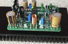
Looks very nice that amp board.
I am willing to help and to learn....i can use a schematic to make a layout for a pcb, but i cant design an amp by my self. If i ever will learn enough to do, dont know...
I learned a lot in this 1 year i am active here in this forum, but i have only a little knowledge in electronic. So, please be patient with me....
I recognize the knowledge that is present here, sometimes I am overwhelmed...😉
The AKSA amp is very interesting, but i don't understand everything in detail. I hope MrHifitunes will built the amp with my pcb and report how it sounds.
Exciting...
Greets
Peter
?Hi
i did not read your thread here .What are Jumper 1 +2 for?
i guess it is for let the VAS and OPS not work and measure the LTP and other voltage parameter?
what happend if we use instead of R1 (15k) a CRD? with e.g. 2mA --E202?
CRD with 2mA
kr
chris
nobody?
thx
chris
Don't know why there is jumper 1 & 2. maybe for debugging? maybe for the one layer layout? maybe @bimo can explain.
I placed the order for the PCBs. thanks @Kleinhorn
I placed the order for the PCBs. thanks @Kleinhorn
Think so too, only Bimo can answer the question. It is not the only schematic he did so. If you have a look to other schematics he made, you will find this jumpers too. At a first look i thought it has only to do with the bias transistor, but there are other components following.
Greets
Peter
Greets
Peter
Why 2mA? Should it not be 4.5 mA? (70[+35V and -35V] /15k) ? Just trying to learn.
Peter can try it. Then it is a full amp board. Proection + bridge and caps. CRC?Nice thread...i read not all
is there a advantage of useing at TGM8 the rail caps directly at the PCB?
jpk73 build a huge PCB with protection and fat "snap in" caps.
kr
chris
I ordered the "Standard" board and will try it with an SMPS. If it is good, I have could have a go at the "full" board ".
2 types maybe ???
- power transistors on one side type
- power transistors on both sides but keeping the board long and slim in size. eg 180mmX55mm.
yes could be... its still R2 in line. so as i wrote...i do not check all the posts.Why 2mA? Should it not be 4.5 mA? (70[+35V and -35V] /15k) ? Just trying to learn.
normally a current of 1mA each transitor is good so i guess 2mA total(for both)
- Home
- Amplifiers
- Solid State
- Based on Hugh Dean's AKSA 55