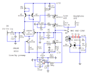
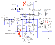
How to split the circuit for 2 power supplies one +/-17v for input , servo and relay and another one +/-30v for output?Peak Max & Peak Min look like they hit the rails. CD red book is 2V RMS max and X10 makes it 20V RMS i.e. 56.6Vpk-pk. Would need +/-30V rails to accommodate that.
Attachments
Last edited:
Don't do anything before I simulate it later on in the day to make sure there's enough drive from the input stage with split stage supplies of so much difference. The output stage adds gain in this circuit, its not a current follower, but lets see if it will hit high rails with acceptable distortion as a whole.
If promising, you will have to hack the PCB rail lanes just before feeding the Mosfets but including the R8 R9 cascode voltage divider. Changing R8 to about 20k keeping around the same M2 gate bias voltage as now. Also, the Mosfets dissipation is going to go way up by applying to them almost double the previous voltage. See to keep them cool, especially M3. And don't push the output stage bias current. You could possibly need extra local rail decoupling caps like C6 C7 or smaller value for the rest (input servo relay) if there will be instability.
If promising, you will have to hack the PCB rail lanes just before feeding the Mosfets but including the R8 R9 cascode voltage divider. Changing R8 to about 20k keeping around the same M2 gate bias voltage as now. Also, the Mosfets dissipation is going to go way up by applying to them almost double the previous voltage. See to keep them cool, especially M3. And don't push the output stage bias current. You could possibly need extra local rail decoupling caps like C6 C7 or smaller value for the rest (input servo relay) if there will be instability.

Thanks Salas!
I will wait for your simulation results .
I'm not in a hurry,all the time is your's!
I will wait for your simulation results .
I'm not in a hurry,all the time is your's!
Thanks Salas!
If you find the time,please can you do the same for gain X10 using existing power supply +/-17v,looking for stability and distortion?
Thanks in advance 😃
If you find the time,please can you do the same for gain X10 using existing power supply +/-17v,looking for stability and distortion?
Thanks in advance 😃
Last edited:
It shows you should not go more than 6X as is if not to overload output with CD source and volume pot at max
If you go to the link below, Salas and I have already discussed raising the rail voltage to 22V and what you need to do. This should allow 7.5X, I think. Maybe good enough?
Rush
But there must also be a 18V same relay type version to use with 22V and the leds (?) Look if available.
Rush

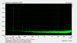
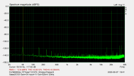
thimios, wonderful results! Can you shed some light on the test setup? Is there any resistance (like a potentiometer) between the generator and the DCG3? I ask this because Salas has indicated that different values of input pots affect the performance. Also, can you test at a higher fundamental, like 10K or 20K? Thanks!
F4 states 12db gain and 10V output. The Lender preamp or something similar seems more appropriate.
Just my 2 cents
Just my 2 cents
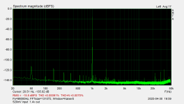
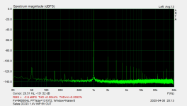
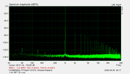
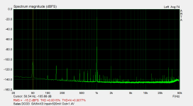
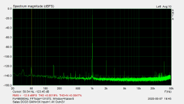
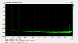
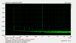
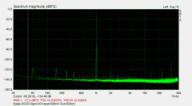
Yes,if you look text right bottom of plots(except the 1st one),input signal is 1.4 v RMS.thimios, wonderful results! Can you shed some light on the test setup? Is there any resistance (like a potentiometer) between the generator and the DCG3? I ask this because Salas has indicated that different values of input pots affect the performance. Also, can you test at a higher fundamental, like 10K or 20K? Thanks!
Output controlled with the volume potentiometer connected at the DCG3 input.
I can do a 10K and 20K fft , maybe tomorrow or today latter.
Thanks Salas,short answer,No DCG3 can't drive the F4 at full power.
I will go for a circuit called,"Yes it can drive the F4".
In the mide time I will restore the DCG3 for pevious gain.
Last edited:
As I have the option to run bothe DCG3 and F4 too, I‘m wondering as to how the addition of YICDTF4 will turn out…
It would take extensive modification to do that. Namely high rails for the stages plus regulation to lower for the servo and delay. Also not practical with dissipation on high rails because of SE Class A. Maybe a three stage circuit with a push pull follower output is better for your purpose.Yes,if you look text right bottom of plots(except the 1st one),input signal is 1.4 v RMS.
Output controlled with the volume potentiometer connected at the DCG3 input.
I can do a 10K and 20K fft , maybe tomorrow or today latter.
Thanks Salas,short answer,No DCG3 can't drive the F4 at full power.
I will go for a circuit called,"Yes it can drive the F4".
In the mide time I will restore the DCG3 for pevious gain.
IMHO just put DCG3 back to 3X and remeasure it to know its back in good order.
*By the way, for your future measurements to drive the F4: As signal voltage rises high it takes an attenuator to avoid audio interface input distortion contribution. Beyond a critical point different to each such interface.
Thimios, if you get the chance you might find the schematics of the Yamaha C1 and C2 preamps a fascinating source for ideas on a driver for your F4.
Friends I'm starting to build a new DCG3. I have a DCSTB power supply board from Tea, but I've seen that some of you have built with UBiB power supplies as well. I have one 100VA transformer (4x 18V AC) and I would like to know what would be the benefit of dual mono power supplies UBiB vs DCSTB.
I'm still deciding, ...thank you!
I'm still deciding, ...thank you!
If you search in this thread for 'UBIB' you will find enough comments. More extended highs and powerful bass, along with bigger soundstage, that what you will expend going with the UBIBs. But it's really system dependent because it could be that you don't want the extra bass or the extended highs.
I tested 4 power supplies, BIBs, UBIBs, DCSTB and ALW super regulator and everyone has some advantages and you can clear hear the differences. I have a preference for dynamic sound so lean more on UBIB which to my ears has more energy
None of them change DCG3's character though, just bring little bit more of this and that.
But is it worth it ? For UBIBs you gonna have to deal with heat and of course the power consumption is twice of the DCSTB.
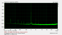
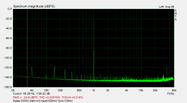
Back to X3 Gain. When measured the X10 Gain to be able to measure this high voltage,I used a divider.
I used the same divider now,but this time isn't needed,so I have to repeat same measurements without the usage of a divider.
If you look closer at the images you can see huge differences in the 50Hz range.
That is because I changed the no name desktop SMPS with a better one from a good supplier.
I used the same divider now,but this time isn't needed,so I have to repeat same measurements without the usage of a divider.
If you look closer at the images you can see huge differences in the 50Hz range.
That is because I changed the no name desktop SMPS with a better one from a good supplier.
Attachments
Last edited:
- Home
- Source & Line
- Analog Line Level
- Salas DCG3 preamp (line & headphone)