
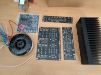
Friends, until my PCBs for the new Wolverine amp arrive, I'm going to start building the DCG3 preamp for the Wolverine. Again and better 🙂
This time I chose one 100W transformer, 4x18V + 1x12V, custom made. Mainly also to save space so I could use a 280mm deep modushop chassis 2U slim line.
I have two questions, I don't want to go through all 369 pages 😢
1. What do you prefer to use for input, better soundstage (uPA68H or LSK369)
2. I will use the ALPS potentiometer, buy 20K or 50K?
Thanks a lot.
Attachments
1. 2SK170BL 😁 https://www.diyaudio.com/community/threads/salas-dcg3-preamp-line-headphone.296406/post-76025621. What do you prefer to use for input, better soundstage (uPA68H or LSK369)
2. I will use the ALPS potentiometer, buy 20K or 50K?
2. 20K
We found in testing initially that the LSK samples did not match as well as uPA68H between their two jfets.
Matched quads of 2SK170BL or 2SK117GR can work well here as well.
I have used ALPs, goldpoint attentuators and TKD, and the latter sounds best here to my ears.
Matched quads of 2SK170BL or 2SK117GR can work well here as well.
I have used ALPs, goldpoint attentuators and TKD, and the latter sounds best here to my ears.
TKD what type?I have used ALPs, goldpoint attentuators and TKD, and the latter sounds best here to my ears.
I am curious about the 2SK170BL option. Is there a recommended Idss if these are used?
From a quick search of the thread, it seems no other substitutions would be required to try this.
From a quick search of the thread, it seems no other substitutions would be required to try this.
Salas, I want to go with R10 at 6.98R (CMF60), will it still be enough to retract 1W? I have a heatsink big enough for such a bias and under the mosfets I will use AL203 pads (15 W/m*K).
Same here. I thought it was just me!2CP-2511
Hi salas Im trying to understand how to use Balanced input in and SE output with once channel as given in diagram. I saw in one of the post. Is there anything that is done in the following diagram on how to connect to get Balanced input and SE output? which pins to short
Attachments
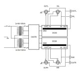
You short no pins in the above diagram. You simply insert incoming and outgoing XLR or RCA connectors from gear as they are.
The trick with this schematic is to connect input XLR pin #1 to circuit ground. Then it still works like two SE channels and you can take what you will need to use at the output. The interesting point is that when you take XLR output, it doesn't need to connect pin #1 to ground. It simply works like this. Bellow is the updated scheme with a balanced volume control. Only XLR input works with that if we want to avoid "bal/unbal" switches. RCA input is connected with a RCA to XLR adapter which makes inputs easy to configure. Outputs have to get a bit different. XLR input to RCA output will leave the volume control out of the game. So The RCA "ground goes to XLR "cold" and it will be grounded at the load side. The 50 ohm inline resistors at the output save DCG3. And headphone bonus. It's all OK for balanced but for TRS a modified socket with two separate sleeves that get shorted when the jack is inserted and 50 ohm resistors is used as the best compromise.

#7,374 showing the correct pin #1 configuration was the tested final without volume control, since at the time I was using the digital VC. However, I had placed 50k resistors from input to ground of each channel, so I guess it works with a quad pot too. SLBs are optional depended on the rest of the system. I kept them on. Final-final -can this ever be? 🙂 - is #7,377 with AVC that shows the 50k resistors too.
R1550 ohms?
- Home
- Source & Line
- Analog Line Level
- Salas DCG3 preamp (line & headphone)