We are the champions 😂Nice to know that you and Nick (post #31) both agree with my conclusion from post #20.
I came in late, missed the earlier postings and first started contributing after reading.
Hans
every MM system is perfectly suitable for a very high-impedance termination.

(...)"then" (...) " is not suitable for"(...)If the 12 dB drop-off that you get with the recommended load is meant to compensate for some mechanical resonance, then the Shure V15-III is not suitable for 150 kohm load, nor for a RIAA amplifier that realizes the 75 us time constant by means of a 4794.5333... ohm load. Not without extra correction filters, that is.
Congratulations on your gold medal. However, the competition committee could quickly take it back from you after a thorough review of the documents you submitted - and then you would be left pretty naked.
Is this insanely evil (mechanical) resonance-point publicly known, do you two know it?
Ms, Lc, rp, Cp, ...
#
If I know the system's behavior, then I can also smooth it out after the EQ preamp. I assume that you both know that. And Hans P., please use kHz and not Khz! Thank you!
According to your post #35, the overall response is about +1 dB at 20 kHz with respect to 1 kHz, presumably with the recommended load.
The transfer from EMF to terminated voltage normalized to 1 kHz increases about 10 dB at 20 kHz when you use a 150 kohm load instead of the recommended load, see post #17 (or 25).
Hence, you get about +11 dB at 20 kHz with respect to 1 kHz with a 150 kohm load. I assume this is due to something mechanical, as I don't know what else it could be due to. Of course it could be corrected with an extra electrical filter if you should want to.
In very old German internet audio forums we can often read about a 33kHz mechanical resonance for the famous Shure MM. Furthermore, a total termination capacitance of <300pF should achieve optimum FR results.
You, we can read there!
It was also stated there that C_term should mainly combat the mechanical influence interaction.
Now comes the solution: the system was praised in the last century for its incredible tracking reliability, i.e. the damper and suspension are softer than usual...! We can read this if we look through ancient press releases, where you can also find corresponding diagrams.
Bye,
HBt.
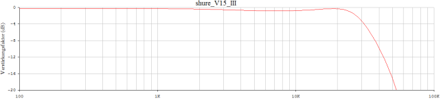
47kOhm || 200pF

fh = f3 >19kHz
The supposed mechanical resonance at 33kHz is now, in addition, very easy to integrate into the model. The model from the neighboring thread.
fh = f3 >19kHz
The supposed mechanical resonance at 33kHz is now, in addition, very easy to integrate into the model. The model from the neighboring thread.
Even after more than 20 years of groundbreaking publication ..., still a very popular topic: MM and the parasitic capacity /Capacitor C_term.
We are the champions 😂
I came in late, missed the earlier postings and first started contributing after reading.
Hans
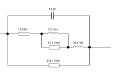
I offer an alternative replacement network:
determined from the famous table of the article "all about noise". However, after detailed data analysis, one must assume that Ltc, the lossless, ideal coil inductance does not correspond to 460mH. 460mH is the value used by the author of the article. This inductance value was probably incorrectly determined with an LCR tester at a frequency of 1kHz; the correct value would have been 407.3Hz (i.e. the 45° point at |Z| equals sqrt(2)*Rdc). It can be assumed that Ltc is 0.51H rounded up. This now also fits slightly better with the standard termination impedance with the familiar 47kOhm. If we know the pointer at f=20kHz and also the lossless pointer, then we can easily determine a third pointer (or vector) mathematically, trigonometrically. This pointer now represents the losses 38.61kOhm +j143.52°. As we intuitively suspect (or simply know), a parasitic capacity is involved /in the game.
Our electric replacement MM could also look like this. Whereby the range of validity of an equivalent two-pole is of course not arbitrary.
HBt.
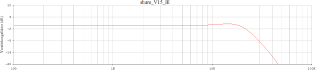
The two-pole must be valid at least between 5kHz and 35kHz, hopefully it is between 1kHz and 100kHz - but two decades? This needs to be checked (but I don't feel like doing that now).
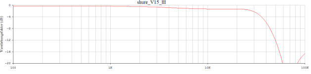
Here are a few results, without the mechanical influence of the stylus - tip and cantilever, damper and the vinyl groove.
Here are a few results, without the mechanical influence of the stylus - tip and cantilever, damper and the vinyl groove.
Attachments

Goededag, Marcel!
I'm back at my attempts to further increase the loop gain.
The 50dB (that were prolonged over 20kHz by means of the T-network) may be bettered up to ~60dB if J310A would control the current mirror loading 2SC2545.
So far I examine that using the ideal V + F (current-controlled current source), and I can easily change the current ratio in the mirror.
I do not see any influence on the noise. But the loop gain is affected somewhat.
In your original circuit J310A has 3.6mA and 2SC2545 has 2.5mA respectively (as per what I see in LTspide at least).
If I do those currents equal - there is ~1,5dB loop gain increase.
What should I look for - regarding the Id and Ic - when using the current mirror in the input diff?
Dankjewel!
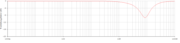
The high-impedance termination, the absolute highlight - and at the same time a limit, considering that Shure itself specifies a value of up to 70kOhm.
Note:
in this example I have taken into account the observed 33kHz resonance of the entire resulting system. Provided that the user voices of the late 20th century are also correct across the board.
HBt.
The electric field of the coils, i.e. the coils themselves and the capacitive parasitic component ..!Yes, I mean the crosstalk curves. What is the non-nonsensical explanation of that behaviour?
EulerThis pointer now represents the losses 38.61kOhm +j143.52°.
The e to the power of j is missing in the correct spelling. Z3 is 38.61kOhm * e^(j143.52°). Sorry.
Some tweaks regarding better correction are required - I'm not good at that.
By using Id of J310A to control the "current mirror" for 2SC2545 it was possible to rise the loop gain by almost 10dB, It is now 61dB @1kHz, and 50dB @72kHz.


The IMD are -85dB relative to the signal (19kHz & 20kHz):

I love this circuit more and more. 😊
By using Id of J310A to control the "current mirror" for 2SC2545 it was possible to rise the loop gain by almost 10dB, It is now 61dB @1kHz, and 50dB @72kHz.
The IMD are -85dB relative to the signal (19kHz & 20kHz):
I love this circuit more and more. 😊
Goededag, Marcel!
I'm back at my attempts to further increase the loop gain.
The 50dB (that were prolonged over 20kHz by means of the T-network) may be bettered up to ~60dB if J310A would control the current mirror loading 2SC2545.
So far I examine that using the ideal V + F (current-controlled current source), and I can easily change the current ratio in the mirror.
I do not see any influence on the noise. But the loop gain is affected somewhat.
In your original circuit J310A has 3.6mA and 2SC2545 has 2.5mA respectively (as per what I see in LTspide at least).
If I do those currents equal - there is ~1,5dB loop gain increase.
What should I look for - regarding the Id and Ic - when using the current mirror in the input diff?
Dankjewel!
Regarding noise, in theory, the higher the drain current through the J310 the better as long as the gate current stays very low, but 3.5 mA should already be pretty good. For the 2SC2545, there should be a noise optimum around 1.913 mA of collector current (at maximum gain), but it's a very broad optimum; when the current is a factor of ten too high or too low, there is still only little degradation.
Regarding intermodulation distortion: how much of it comes from the very simple voltage follower, Q9 in your schematic?
Goededag, Marcel!
Thank you for the clarification.
Now I check what's going on regarding the PSRR.
The negative bus is not so horrible, the positive - is really awfull. I'm trying to devise something about that.
Thank you for the clarification.
Now I check what's going on regarding the PSRR.
The negative bus is not so horrible, the positive - is really awfull. I'm trying to devise something about that.
Sometimes you have to take a little more time than usual, in the modern digital 4.0 world you no longer read, but skim the text in search of the key information. In plain language, this means for me: I read Marcel's article published in 2003 again at my leisure and let it sink in.
Attached is the extensive discrete test circuit of the article for free use. It looks wild and complicated at first glance, but is actually a very simple number.
Nevertheless, many thanks to Marcel vdG. for the brain food. This muesli has already been metabolized and is now water under the bridge.
Good luck "KT315A" with your venture and maybe it will become a real (and rebuildable) project.
HBt.
Attachments

With both input and second stages !You don't get the cancellation you would get with a symmetrical differential pair
- Home
- Source & Line
- Analogue Source
- I'm interested in RIAA preamps design