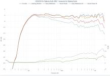
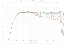
In case you didn't use this before, as pointed out earlier in this thread, the document written by Kimmosto shared in this earlier post is incredibly helpful in the sound balancing process. Especially useful are the general slope recommendations for each of those curves in the spinorama plot:
Post in thread 'Budget Classic 3-way Discussion Thread' https://www.diyaudio.com/community/...c-3-way-discussion-thread.423939/post-7945823

Worst case scenario... 😱
It appears as if Z-axis was not accounted for.
The mild peak around 1k and slighy recession at 3 - 4 k off axis helps the speaker to not sound aggressive when playing it louder. The trend of the mid recession increasing slightly further off axis makes the speakers tunable using toe in / out.Would you mind explaining this further? Thanks!
Why would you do that?... if you put it in séries with woofer
The high-value inductor is needed to compensate the low-frequency impedance peak that would otherwise interfere with the low-pass. Take another look at the circuit.
The sim is derived from the Gema kit: baffle and coordinates are the same, I just replaced the sb34 with the SLS and reduced the volume of the mid cabinet to 1.2L.Darn, no thread or sim on here can ditch the marmite cockroach NRX 😡
WF120BD04, etc?
Marmite??? Please explain, do you mean that the nrx series sound just like this...
It's just a simulation to see if everything could work well. Generally, I assume that the drivers are measured in the same way, especially if the manufacturer is the same, and that should include the time of flying from the driver to the mic.It appears as if Z-axis was not accounted for.
It is not a stepped front baffle, is it?It appears as if Z-axis was not accounted for.
This project is meant to have a flat vertical baffle, any generic manufacturer graph sims should account for Z-axis as well.
But first things first.
But first things first.
^ Didn't realize the sim was with mfct graphs, just glanced and thought it was actually measured....
I was thinking about what seems to be th t-bass technic.Why would you do that?
The high-value inductor is needed to compensate the low-frequency impedance peak that would otherwise interfere with the low-pass. Take another look at the circuit.
Thread 'Open Baffle Bass Boost: +4 to +7dB w/ Passive Xover, No DSP' https://www.diyaudio.com/community/...boost-4-to-7db-w-passive-xover-no-dsp.404171/
The 'T' bass circuit is attached in open baffle form.
A first construction using the values shown will give an idea of its capabilities.
The 2x 470uF (low ESR electrolytic) capacitor tunes the choke to the baffle/rear reflection peak which can become obtrusive around 100-120Hz. This can allow an OB to be moved further back into a corner. Try different capacitor values to adjust the 'cut' frequency.
The cut runs from around/above driver Fs and becomes maximum at the baffle/room corner SPL peak frequency. The resistor in series with the capacitor controls the degree of cut at this...
It seems some people have done this in sealed enclosure too.
I did that some time ago, here is the Hornresp simulation:Nobody thought of a passive 3d order tuning for the 12” SLS?

and group delay:

Last edited:
After breakfast I will check my shop and see what I have on-hand... I think I have some XPS material. More importantly, I am pretty sure I still have the small plywood test baffle for the SB12MNRX, which has the correct recess and hole. If so, all I need to do is build an XPS foam box around the plywood test baffle.Consider whether mocking up a similar XPS foam board would be worthwhile for the SB12MNRX - it won't be exact, but it will at least be comparable to the 4" and 5" drivers that I measure.
j.
80 euros with shipping from Ali...??
I think it was clear that we can forget it. Nobody are stocking them in Europe.
But okay, let's forget it according op wisches; my not interrested vote is there are chance veryone agree with the Discovery 15.
In my own recent, still learning from experience, trials... a 500Hz bump in response, which guessing often from baffle/diffraction effect, gives annoying slappy upper bass sound. Take it away and sounds golden, cleaner. Regardless, this thread has been been very informative with nuggets of wisdom.
still there at 3 meters in a living room ?
Your sim was great. I am of the opinion that the NRX sounds like ***, yet it's ubiquitous here (this forum, hence cockroach). Marmite is a weird foodstuff from the UK; it's a savory spread made from yeast extract. Their whole ad campaign is based on saying "Marmite! You either love it or hate it!" To some, it tastes like absolute ***, but some people enjoy it and spread it on their toast.The sim is derived from the Gema kit: baffle and coordinates are the same, I just replaced the sb34 with the SLS and reduced the volume of the mid cabinet to 1.2L.
Marmite??? Please explain, do you mean that the nrx series sound just like this...
View attachment 1431924
It's a little like the Champagne, but less ligth...😉
Let's sim with the 15w disco and the HDS PP ?
Let's sim with the 15w disco and the HDS PP ?
Are you able to show us visual measurements, or let us listen to the residuals of the SB17NRX2 driver?
@DcibeL has recordings of the SB15NRXC30-8-UC, it is the very first version of this driver, with an uncoated cone. It would be unusual for an up to date, slightly larger version, to perform poorly compared to the very first generation.
Out of box free air measurements or in-box measurements, on axis and/or off axis measurements, with ESS or FSAF welcome.
The way that high frequency directivity rises makes me wonder how a coaxial would perform on the monkey casket. SICA 5,5 C 1,5 CP. SICA has a tweeter/mid crossover premade for it and it's pretty inexpensive compared to a Scan-Speak/SB Acoustics mid/tweeter combo.
The original monkey makers used tweeter over mid but if they had modern tech coaxials would they have gone that route instead to get the free waveguide? (if real waveguides are restricted on this project)
Attachments
Funny I has the same idea with Sica coax this morning 🙂 My choice will be 6,5" to match 12" better. Imho good fit to sls12 with bucking magnet. My concern is consistency - had few of them in my hands and some had different polepiece, some had not so good tweeter to cone area, ...
Last edited:
My approach with a Sica 5.5inch coax/6.5inch coax/another suitable coax for a given budget would be to have dual 8ish inch woofers helping with bottom end and the coax itself either with cardioid side/front vents (only for the mids and not the bass) or even without cardioid vents (just for simplicity of design). A shaped baffle around the coax would help with some amount of proper "termination" of the waveguide formed by the coax mid driver for the tweeter. Another optimization could be to properly dimension the width and depth of the speaker for overall directivity goals. In short my idea of that project would look like the speaker shown in MrStitcha's excellent thread with the KEF coax replaced by another suitable and available coax.

It would look nicer (to me), can have relatively higher sensitivity and maybe other benefits in terms "looks of those performance graphs". Maybe it can even be put on its side and called a center speaker in a multichannel set up if one needs to do something like that 🙂
Given the expertise that we have on this forum and the technology available these days in terms of simulations and manufacturing these kind of cabinets, I think it is definitely doable and more exciting (for me atleast).
But the title of that thread would "high performance 3way on a medium budget".. 😉
Anyway, I am stopping the diversions from the main theme of this thread 🙂
Last edited:
- Home
- Loudspeakers
- Multi-Way
- Budget Classic 3-way Discussion Thread