same SL OS both
M25 - SE input only, autoformer based FE, No NFB, gain either 4 (Cinemag, Jensen classic repeaters) or 6 (Edcor 600:15K), mild THD, dominant 2nd neg
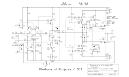
PoP - active FE, both SE and Bal input, NFB yes, gain - forgot ........ aha - 100K/10K, loow THD, dominant 2nd neg
sound - all my amps are sounding the same

M25 - SE input only, autoformer based FE, No NFB, gain either 4 (Cinemag, Jensen classic repeaters) or 6 (Edcor 600:15K), mild THD, dominant 2nd neg
PoP - active FE, both SE and Bal input, NFB yes, gain - forgot ........ aha - 100K/10K, loow THD, dominant 2nd neg
sound - all my amps are sounding the same

other OS parts - they will work, but with slight difference, if there is a difference in xconductance, comparing to originally used
slight - no night and day
though, clever to use mosfets in output, as is constructed ........... TTC/TTA are bipolars
availability - you're practically just one personal message away of knowing how
slight - no night and day
though, clever to use mosfets in output, as is constructed ........... TTC/TTA are bipolars
availability - you're practically just one personal message away of knowing how
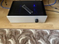
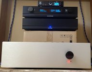
A close friend of mine liked the Mini so much that he wanted one too.
I hope he will like the outcome 😎
I hope he will like the outcome 😎
Attachments
-
 IMG_6835.jpeg805.9 KB · Views: 144
 -
 IMG_6912.jpeg666.5 KB · Views: 152
 -
 IMG_6911.jpeg409.1 KB · Views: 146
 -
 IMG_6901.jpeg661.8 KB · Views: 149
 -
 IMG_6900.jpeg481.8 KB · Views: 150
 -
 IMG_6894.jpeg491.1 KB · Views: 146
 -
 F5EB7A46-EA34-4243-912D-7F9F75A9F303.jpeg363.4 KB · Views: 158
 -
 C8BFBEFA-9A37-47C1-A890-A459A6636FA2.jpeg488.2 KB · Views: 160
 -
 IMG_6840.jpeg395 KB · Views: 152
 -
 IMG_6839.jpeg784.7 KB · Views: 156
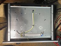
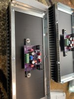
matter of principle - if sending wires though metal plate, always do it in "natural pair through one hole" fashion, using grommets
example: [L & N] wire through same grommet-ed hole
example 2: [+, GND, -] through same grommet-ed hole
btw. which amp is that?
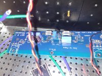
if PoP, I'm glad seeing someone else's pcbs
I'm famous!!

example: [L & N] wire through same grommet-ed hole
example 2: [+, GND, -] through same grommet-ed hole
btw. which amp is that?
if PoP, I'm glad seeing someone else's pcbs
I'm famous!!

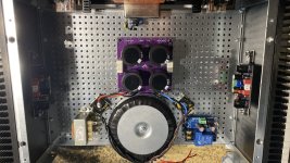
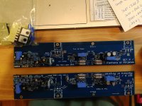
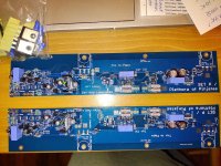
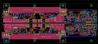
So far so good, hopefully. Here's boards, no ccs board yet, but thought I would post for more eyes to find my ook ups. Did I leave anything out?
This is standard P of P, not set version.....
TIA,
Russellc
This is standard P of P, not set version.....
TIA,
Russellc
Attachments

On initial fireup, does this follow XA 252 method, both neg and pos inputs grounded, grounding jacks in amp input. Solder blob across
S101 and S201, Jumper in place? Oh, this is straight mosfet version, NOT SET.
Russellc
S101 and S201, Jumper in place? Oh, this is straight mosfet version, NOT SET.
Russellc
yup for everything
I believe you got separate sch files in fileset I sent you, so just strictly follow one for straight MOS
I mean, I don't remember, but it's logical that I did
for start, while setting Iq, no jumper across cap in negative input leg, only later
I believe you got separate sch files in fileset I sent you, so just strictly follow one for straight MOS
I mean, I don't remember, but it's logical that I did
for start, while setting Iq, no jumper across cap in negative input leg, only later
Oh, I remembered it backwards. So, no close of JP101 and JP201 at fireup, closed once done.
Is this also like XA 252 that no power down required for closing JP 101 and JP 202?
Thanks,
Russellc
Is this also like XA 252 that no power down required for closing JP 101 and JP 202?
Thanks,
Russellc
Checking file set, only notes are what parts to exclude, short S101 and what resistor to use in another position. Dont see any other notes, although
I do see two additional tabs on that note file, unfortunately they had nothing in them. I went through the other files, I could just be too dense to locate, but seems logical they would be in the "notes" part.
Russellc
I do see two additional tabs on that note file, unfortunately they had nothing in them. I went through the other files, I could just be too dense to locate, but seems logical they would be in the "notes" part.
Russellc
Note:
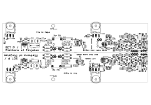
Plethora of Pinjatas, DO NOT MOUNT:
DO NOT MOUNT ZD103, R142, M101, R144, R149, Q109, R143, R145, R146, T108
R147=100R
SHORT S101
Plethora of Pinjatas_SET: MOUNT all of above
R147=750R
OPEN S101
Plethora of Pinjatas, DO NOT MOUNT:
DO NOT MOUNT ZD103, R142, M101, R144, R149, Q109, R143, R145, R146, T108
R147=100R
SHORT S101
Plethora of Pinjatas_SET: MOUNT all of above
R147=750R
OPEN S101
Attachments
-
Plethora of Pinjatas_SET parts placement.pdf58.3 KB · Views: 45
-
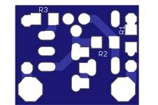 LM334 CCS bottom render.png200.9 KB · Views: 97
 -
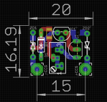 LM334 CCS Eagle sshot.png53.5 KB · Views: 65
 -
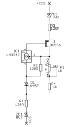 LM334 CCS schm.png145.2 KB · Views: 63
 -
 Plethora of Pinjatas_SET Eagle sshot.png150.4 KB · Views: 87
 -
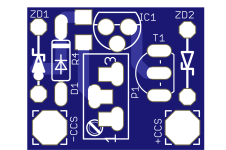 LM334 CCS top render.png272.5 KB · Views: 69
 -
 Plethora of Pinjatas_SET parts placement.png393.7 KB · Views: 111
 -
 Plethora of Pinjatas_SET schematic.png273.7 KB · Views: 108
 -
Plethora of Pinjatas_SET NOTES.txt215 bytes · Views: 43
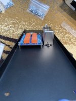
Yes. Let me post pic.did you soldered small CCS daughterboard pcbs on big pcb?
Attachments
- Home
- Amplifiers
- Pass Labs
- Plethora of Pinjatas / SET P amp(s)