Vunce , Thanks for your support with this surprise issue .
I've been meaning to say , looking at your USSA Amp , you obviously have a huge skill set in fabricating projects .
Since Aluminum Oxide Ceramic pads are between 1 mm and 2mm thick , I did not want to risk moving the solder joints on the Exicon MOSFET's .
Also , I bent the leads of the MOSFET's around a 1/4" drill bit - so there is a gradual bend of the leads .
I used 6mm long stand offs , so there was no play in moving the MOSFET's closer to the USSA board .
However ... , I realize now another opinion would be to buy longer standoffs for the USSA boards , and mount the driver MOSFET's on pads too .
So in other words , raise everything the the thickness of those Aluminum Oxide Ceramic Pads .
But in the end , I paid the silly price for these
https://www.mouser.ca/ProductDetail/951-SPA2000-01500104
Shipping with mouser is free over $100 Cdn ( $70 US ... soon to be $34 US ) so I bought other components to get the free shipping .
Plus I trust Mouser , Newark , ABRA , DIYAudio Stores and other recognized vendors that they aren't going to sell fake components .
The main concern is the thermal conductivity of the pads I bought .
.

You should buy a batch of the ceramic insulators and keep them in your stash for the next build. They work excellent and are reusable, used with goop I've never had an issue. The 0.65mm are a bit thin and can crack if the heatsink isn't prepped with care and 2mm is way too thick.
Just like Goldilocks said "This 1mm insulator is just right." Hahaha! 🤣
Just like Goldilocks said "This 1mm insulator is just right." Hahaha! 🤣
Anatech , Brijac ,
I realize now the easiest solution would have been to buy the 1mm or 2mm thick Aluminum Oxide Ceramic pads
and buy longer stand offs .
Anyway , these are on the way . The data sheet says they have high thermal conductivity .
https://www.mouser.com/datasheet/2/48/BERGQUIST_SIL_PAD_TSP_A3000_en_GL-3433303.pdf
As long as they work fine I don't care about the price .
I've heard the USSA 3.2 Amp - the right channel only - driving a B&W 110 speaker .
For some unknown reason it didn't short out without the thermal pads .
The transient response of a piano , alto sax , snare drum was so good I didn't want to take the test set up apart .
I was going to end up with a Right Channel only system , with the heat sink sitting on my work bench .
The Amp was so quiet , I could put my ear into the mid/bass driver and couldn't tell the USSA 3.2 was on until the music started .
But ... it sounded better at different times of the day . So rather than using a CRC power supply board ,
I went with a CLrRC board . Not sure if the chokes need some shielding .
.
Hi Uunderhill,
Anodizing is an oxide layer on the metal. it isn't conductive, but has a low punch-through value. Any debris or surface roughness can cause a short. High enough voltage will definitely do it.
I have had equipment come in for service missing insulators. They may eventually short. Often they sort sooner than later. Thermal grease adds to the insulation.
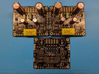
Last year I bought these PCBs from a long time diyaudio member who got ill and had to sell his stuff. Unfortunately these PCBs come with no BOM or instructions on build and start up. I would appreciate if anyone can provide some information on these boards. I would like to start building these, I also understand I will need a power supply for these, any pointers would be appreciated. I found a link to another thread for power supply and it looks that thread is last updated in 2023.
Attachments
Eliad,
The USSA-5 is Fab's design and he would be able to help you out with the bill of materials.
The image shows 3 PCBs and 2 of them have a good number of components already loaded on to them. Did you get 3 PCBs from the diyAudio member? Did he provide you with any list of parts that he had installed or any bill of materials?
I got these when a diyAudio member, spaceistheplace, got ill and a friend of his helped him sell his stuff. This is all I got, no other information, just these boards and the power transistors. As far as I know spaceistheplace is no longer active which is really sad. He is a very nice guy, I hope he is ok.
It doesnt bother me I probably overpaid for these, I helped a guy in need but now I am stuck with these. I would like to complete this project if possible.
It doesnt bother me I probably overpaid for these, I helped a guy in need but now I am stuck with these. I would like to complete this project if possible.
Sorry to hear about diyAudio member spaceistheplace. Hope he is ok.
Let's wait a little and let Fab chime in. I am pretty sure the community can get you up and running.
In the meantime, let's look at the other parts - do you have a chassis and power transformers for the potential build?
Let's wait a little and let Fab chime in. I am pretty sure the community can get you up and running.
In the meantime, let's look at the other parts - do you have a chassis and power transformers for the potential build?
I just started this project. Looking at this thread I see i will need a transformer 2x22V or about and a high VAC but I am not sure about it since I dont have all the information. I also see for the chassis I need to have good heat sinks. But this is all that I can gather, if you have suggestions they will be greatly appreciated.
@Eliad,
Just to clarify - the PCBs that you have can be used for multiple variants of USSA. 🙂
So Fab will try to understand from you that which version was being built by the previous builder. If you are not clear, he possibly will ask some questions on component values/numbers and that will give him more insights.
So better get the PMs with him started.
Good luck!
Eliad ,
As Fab pointed out , these are USSA 5.x Amps that have been started . So my 2 cents
1 ) You've pointed out that you received the power transistors . To double check ,
2sk2013y and 2sj313y driver MOSFET 's have been discontinued .... were these included ?
What are the part numbers on the larger MOSFET's ?
2) FAB has graciously put a booklet together with the schematic , BOM , building and testing info .
3 ) As Vunce advised me , highly recommend going with dual power supplies , using LT4320 and MOSFET 's as diodes .
( I already had a DIYAudio Stores V3 mono power supply on the way )
4 ) There are now over a 100 pages here , but there is a wealth of experience . So slug through the 100 pages ,
and copy and paste important comments onto a word file .
5) Sourcing all the components is a total PIA . However , I've heard the USSA 3.2 . Building this Amp is well worth your time and effort .
6 ) Have you built other audio projects before ? Having the experience of building Nelson Pass's F5 would really help .
.
Last edited:
Fab was very gracious and replied to my PM. Great guy.
I started my journey in electronics about 2 years ago,. So far I build vacuum tubes preamps and power amp. I have so much more to learn, I am humbled by the amount of knowledge I have to still learn.
Recently I build a pair of speakers for my workspace and it turned out they are no that sensitive for a 10W output vacuum power amp. I need a little more power to drive those speakers and I recalled I bought these USSA-5 PCBs and looked at them and realized I dont have much information on them.
For my main audio I build Klipsch Belle clones which work great with low power vacuum power amp.
After reading the manual and looking at what i have, I think I figured out what version i have. I believe is 5.1.
At the input I have BC550 and BC650
I have the following components.
Matched Quads 2SK170-BL
Mosfets
K2013x2
J313x2
Drivers
ECW20P20-S x4
Am I correct in my assumption this is 5.1?
Double check the Exicon Lateral Mosfet part numbers
You should have:
ECW20N20-S x2
ECW20P20-S x2
Good luck with your build!
Fabs USSA-5 is a wonderful amp to have in your stable.

You should have:
ECW20N20-S x2
ECW20P20-S x2
Good luck with your build!
Fabs USSA-5 is a wonderful amp to have in your stable.
My bad, I didnt pay attention. I have the correct Exicon, 2 of each.
I checked the resistors which are installed on the board. There are a couple of resistors which are different value(R7, R8 and R13, R14), I think what i have is ver 5. I will desolder those 4 resistors and replace them with ver 5.1 resistors. Unless I dont understand the differences between 5. and 5.1
Also I see on the BOM RV1a,b and RV2a,b could be anywhere between 0 to 100 Ohms. What should I have on hand for testing?
Hello Eliad
The USSA-5 is an exceptional amplifier and if you complete its construction, you will not regret it. However, follow the steps of manufacturing, verification and adjustments described in the manual to guarantee success.
The USSA-5 is an exceptional amplifier and if you complete its construction, you will not regret it. However, follow the steps of manufacturing, verification and adjustments described in the manual to guarantee success.
I started reading the thread from very beginning, i am at page 10, 100 more to go. So far very exciting.
I am trying to decide first of all on the transformers and CRC power supply, any suggestions? Then next step would be the chassis. I see a recommendation for 3U 400mm but I will wait on the chassis until I determine the transformers and the CRC power supply.
I am trying to decide first of all on the transformers and CRC power supply, any suggestions? Then next step would be the chassis. I see a recommendation for 3U 400mm but I will wait on the chassis until I determine the transformers and the CRC power supply.
- Home
- Amplifiers
- Solid State
- USSA-5 Build with Review