Hi Uunderhill,
Thank you for the link. Downloaded, you never stop learning.
Horizontal fins are for aesthetics mostly, without regard to reliability. They are effective with forced air cooling, two speeds normally. Never fail to use thermal cutout switches if you are using a fan cooled system.
Commercial amplifiers often use heat sinks that are not efficient enough (shipping weight, material cost). Marantz and Yamaha MI are the last brands I worked on with thermal headroom. Those things are solid, so keep that in mind.
Yes, absolutely pay attention to inside chassis temperatures! Some parts or circuit areas will run a lot warmer than others. You don't really want to use a fan as it makes your amp into a vacuum cleaner! lol!
" ... you never stop learning. "
People on this forum have life times of experience designing and building amps , so its a good idea to ask them questions and learn from them .
Plus its far more enjoyable bouncing ideas off each other .
With the heat sinks made by multicomp , I was sitting on the fence of whether to go with
MP008442 rated at 0.42oC / W ( 300 mm x 100 mm x 40 mm )
MP008443 rated at 0.36oC / W ( 300 mm x 150 mm x 40 mm )
But after thinking about your comment concerning temp affecting component failure rate , and reading through the discussion that starts on pg 10
https://www.diyaudio.com/community/threads/ussa-5-build-with-review.323778/page-10
think its best to go with the 0.36oC / W heat sink
Both these heat sinks have a 10 mm thick back plate , which will improve thermal conductivity from the MOSFET's to the actual fins ,
But .... this plate of aluminum will also act as a big thermal capacitor - which means the amp will take a while to reach its operating temp .
.
So I ordered 2 of these heat sinks from Newark
MP008443 were $72 Cdn each , then with shipping and taxes were a total of $176 Cdn , hopefully I won't dinged with a brokerage fee .
.
Yes, you're absolutely correct. The mass of the heat sink will act as a kind of "thermal capacitor". But the rate of heat loss to the air depends on the fin depth, thickness and pitch. It isn't a bad thing to have the outputs rise more slowly to operating temperature.
It's the current and not the temperature that sets the operating point. If bias takes a while to settle down - okay. Some amps (ie: some Marantz) have a slightly negative temperature coefficient for bias current, others slightly positive. These will vary with ambient temperatures and how much energy you are dissipating (amp cranked?). Well designed amplifiers will have bias currents that remain in a range close to set point. So while temperature can vary the bias current a little, it shouldn't be a problem. Bias is an approximate thing anyway unless you set it to that critical point some amps have for minimum distortion. Even then things don't change a lot unless you go to underbias.
I'd go with the 0.36 °C/watt. If you were me, you would get nailed for duties. Digikey covers all of that, so they would come in without extra owing. I can't remember on Newark.
Just out of interest , I connected 0R2 resistor in series with a 12 Vdc brushless motor computer fan
and had a look at this on a scope . The scope was showing a - 80 mVdc voltage spike .
As a general rule , great care should be taken when mixing motors and analog electronics .
.
and had a look at this on a scope . The scope was showing a - 80 mVdc voltage spike .
As a general rule , great care should be taken when mixing motors and analog electronics .
.
Yes, separate power supplies. Those were commutating spikes. Electronic switching instead of brushes. So that would appear in the power supply as current changes, and those wires can certainly induce noise elsewhere. Lead dress can be so critical.
So looking at ACG's thermal image photos , post #426 , pg 22
and FAB's measurements for the mounting holes , post #449 , pg 23
cl00sed's measurements for the mounting holes , post #450 , pg 23
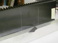
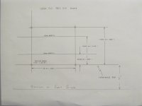
Here is what what I did to scribe the lines for the mounting holes for the USSA 5.0 REV 0.4 board .
- I used a 1 x 2 " piece of architectural tubing , and ran a utility knife blade along it to scribe a reference line along the bottom
- Note how the caliper is made from stainless steel , so it can be used to measure and scribe into the aluminum heat sinks
Don't bother buying a digital read out caliper gauge , an imperial dial caliper gauge is all you need .
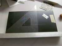
- with the architectural tubing at the bottom of the heat sink , ran 2 vertical lines with a set square , and scribed them with a single sided razor blade
- PLEASE NOTE : Your fingers are never in the path of any blade ever . I've seen more accidents with hand tools than anything else .
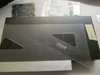
- For the horizontal lines , the lines are automatically parallel by sliding one set square along another set square
- note how I bent the leads of the transistors around a pen or AAA battery ( For brake lines , use a beer bottle )
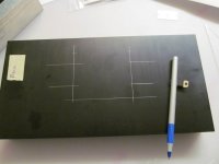
- scribe all the lines before drilling
.
and FAB's measurements for the mounting holes , post #449 , pg 23
cl00sed's measurements for the mounting holes , post #450 , pg 23
Here is what what I did to scribe the lines for the mounting holes for the USSA 5.0 REV 0.4 board .
- I used a 1 x 2 " piece of architectural tubing , and ran a utility knife blade along it to scribe a reference line along the bottom
- Note how the caliper is made from stainless steel , so it can be used to measure and scribe into the aluminum heat sinks
Don't bother buying a digital read out caliper gauge , an imperial dial caliper gauge is all you need .
- with the architectural tubing at the bottom of the heat sink , ran 2 vertical lines with a set square , and scribed them with a single sided razor blade
- PLEASE NOTE : Your fingers are never in the path of any blade ever . I've seen more accidents with hand tools than anything else .
- For the horizontal lines , the lines are automatically parallel by sliding one set square along another set square
- note how I bent the leads of the transistors around a pen or AAA battery ( For brake lines , use a beer bottle )
- scribe all the lines before drilling
.
Attachments
-
 USSA 5 - heat sink reference line.jpg128.8 KB · Views: 97
 -
 USSA 5 Heat Sink - scribing vertical lines.jpg133.1 KB · Views: 81
 -
 USSA 5 - scibing paralle lines with 2 set squares.jpg147.3 KB · Views: 77
 -
 USSA 5 T0-220 leads bent around a pen.jpg117.9 KB · Views: 94
 -
 USSA 5.0 Rev 0.4 drill hole locations.jpg98.9 KB · Views: 91
Last edited:

I'm too lazy and just tape the bare pcb to the heatsink and go to the drill press. Drill the 4 mounting hole, remove the pcb, then tap the holes and screw in brass standoffs. Bend the legs of the transistors, insert them in the bare pcb and mount the pcb to the standoffs, mark the exact locations of the transistor mounting holes. Remove everything from the heatsink, hit the marks with a punch, drill and tap holes. Heatsink is ready for duty 😉.
Vunce ,
Running a reference line , and all the measures and cuts are made with respect to the reference line is very basic standard practice .
Then using an imperial dial caliper to measure and scribe is very easy .
https://www.leevalley.com/en-ca/sho...09-stainless-steel-dial-calipers?item=88N7201
Using a reference line avoids compound measurement errors .
Sliding 1 set squares along another , to mark parallel lines , is also very simple trick .
Often a machinist will coat the metal with a blue ink so they can see the scribe lines easier .
Once you get used to used to measuring with a dial caliper , and using simple set square tricks , it becomes automatic .
Its like using a scope , it just becomes second nature .
.
Thanks for adding the link for the dial caliper, I should’ve had this in my toolbox already.😉
Vunce ,
Actually , I just checked on line and a made in USA Starrett is not as expensive as I though it would be .
Shopping around , it can probably found for a better price .
https://www.grainger.ca/en/product/...M5vSIWuqShZr4uYgmroaAlXrEALw_wcB&gclsrc=aw.ds
Starrett is the equivalent of buying a Fluke multimeter .
Don't bother buying a digital read out one , vernier , or metric - an imperial dial gauge is the way to go ( real measurement )
Saying that , a quick conversion to know is 1 mm = approx 0.040 "
.
Last edited:
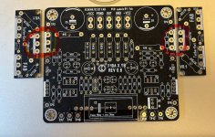
Might not be the thread to ask, but, anyone got USSA-5 pcb pair spare (black would be amazing 🤞😁), version with 2sk2013/2sj313?
I still have ussa5.xB version PCBs. This is the version with BJT as outputs because of translstors different pin out of Lateral mosfets. Lateral mosfet can still be used swapping 2 pins….or use my current extender board PCB also used for twin turbo version…. This version uses any drivers listed in the table of the USSA5 PCB group buy thread so including the
2sk2013/2sj313.
Fab
2sk2013/2sj313.
Fab
Attachments
Last edited:
To point out , Profusion usually ships by DHL and the courier cost is a bit silly .
However , I phoned Profusion and asked them if they would ship by Royal Mail .
They were good with this. So the shipping cost for 8 MOSFET 's , by Royal Mail was $9
with a tracking number . I did not get dinged with a brokerage fee .
So I was checking my emails , and got an email from Royal Mail
saying the MOSFET's had been delivered .
So they knew in Britain , that the MOSFET's were sitting in my mail box in Canada
before I did .... and I was 12 feet away from my mail box .
From North America , the actual phone number to dial for Profusion is 011 44 1702 543500
They are 5 hours a head of EST .
.
Just seeing this, sorry. I have a weird OCD to keep things tidy and flawless if possible 😅 Any chance of GB in the future? It is of no rush to make this amp asap i can wait 🙂I still have ussa5.xB version PCBs. This is the version with BJT as outputs because of translstors different pin out of Lateral mosfets. Lateral mosfet can still be used swapping 2 pins….or use my current extender board PCB also used for twin turbo version…. This version uses any drivers listed in the table of the USSA5 PCB group buy thread so including the
2sk2013/2sj313.
Fab
Hi
For the USSA builders, if you have some time for an small encouragement, you can view this video, put a like or dislike ….🙄) and a small comment on the appreciation of the video itself. If you check at about 5:40 you may understand why…..😉
You can even also ask your fiends too…🙂
thanks
Fab
For the USSA builders, if you have some time for an small encouragement, you can view this video, put a like or dislike ….🙄) and a small comment on the appreciation of the video itself. If you check at about 5:40 you may understand why…..😉
You can even also ask your fiends too…🙂
thanks
Fab
Last edited:
Congrats Fab!!!
USSA5 bloodline, should be a fantastic commercial amp 🥳.
USSA5 bloodline, should be a fantastic commercial amp 🥳.
Thanks Vunce!
In fact, it is USSA-X….. 😉
Do not forget a small comment on the video itself…
Fab
In fact, it is USSA-X….. 😉
Do not forget a small comment on the video itself…
Fab
- Home
- Amplifiers
- Solid State
- USSA-5 Build with Review