Vunce ,
Thanks for the heads up about AnTek transformers and ordering from Toriody .
From building a number of preamps , when selecting a transformer , IMO having low capacitive coupling between the primaries
and secondaries is important . For this reason , I go with split bobbin transformers with preamps .
Looks like the AnTek AU - 7818 is wound for high efficiency - so it would have having low capacitive coupling - think you saved my bacon on this one .
I've bought AnTek 100 VA transformers with the shield - but couldn't hear any difference if the shield was left floating or connected
to Hydro Earth - IMO Hydro Earth is quite noisy . I didn't try connecting the shield between the primaries and secondaries to analog ground .
AnTek makes an AN - 6218 , so I'll probably go with this .
Rather than shield between the primaries and secondaries , I've the found the DIY Fo Felix EMI filter to make a significant improvement .
Highly recommend building one of these and giving it a try .
Briefly looking at makes of other toriods , the limit for dual 18 v + 18 v secondaries , is typically around 250 VA or 300 VA .
So now I understand one good reason of going with dual mono power supplies for this USSA Amps ,
as well as being able to shorten the lengths of the high current wiring .
Project16 says there were dual mono CRC power supply boards made that match USSA Amps .
https://www.diyaudio.com/community/threads/crc-power-supply-class-a-amplifier.301682/
But I've already got a DIYAudio Stores V3 power supply board , all populated and set up for an CLrRC filter .
.
Uunderhill,
For a dual-mono set up, you will need 2 power supply PCBs - are you able to fit 2 x DIYAudio Store V3 PSU boards in your chassis?
For a dual-mono set up, you will need 2 power supply PCBs - are you able to fit 2 x DIYAudio Store V3 PSU boards in your chassis?
Zman01 ,
I'm just in the middle of another project right now , so I have to zoom
Making sure there is enough real estate inside the box is an issue that is easy to over look .
The Short Answer - for the USSA 5 , using CRC power supplies .
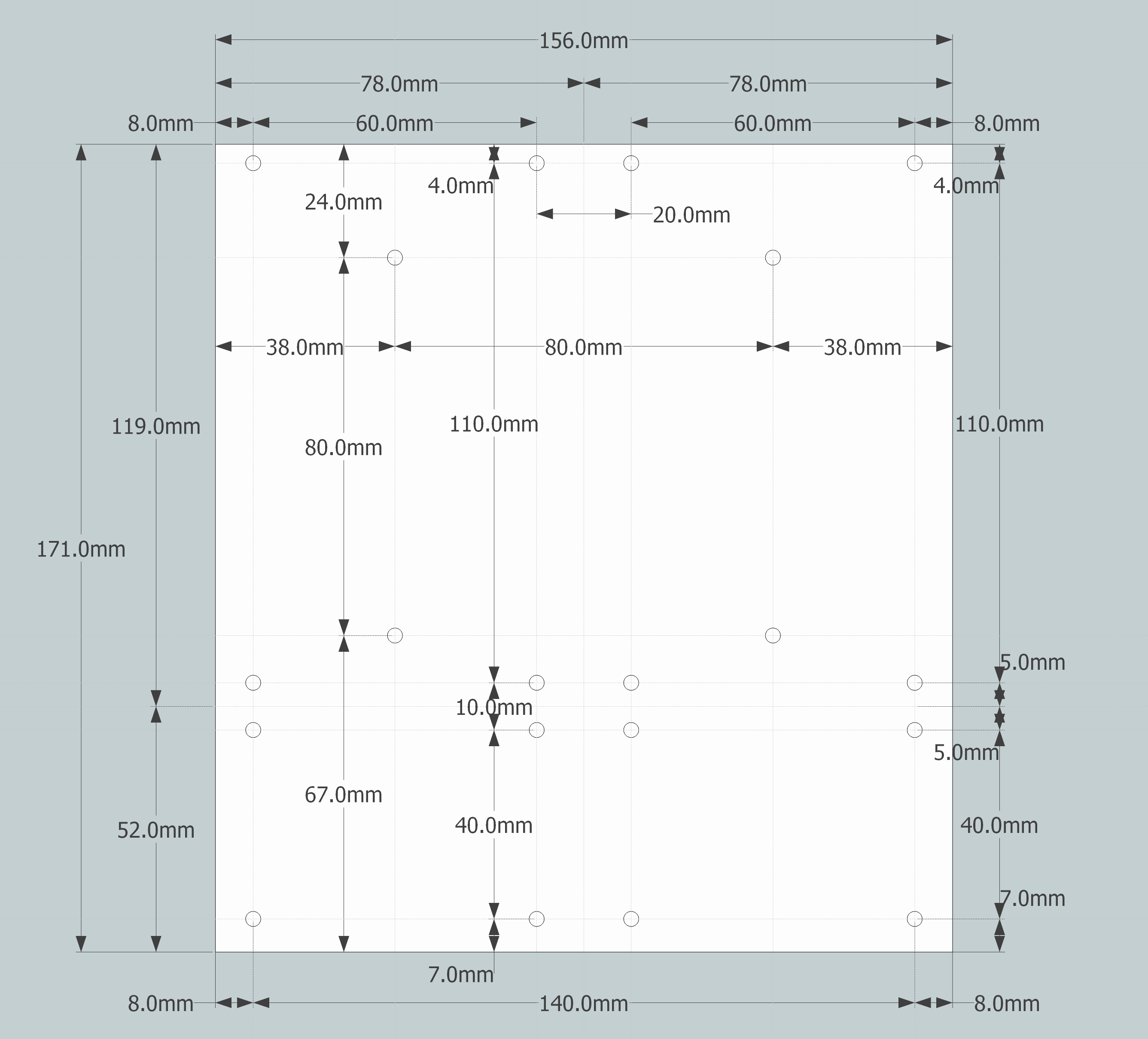
Here are the dimensions for the V3 board .
https://www.diyaudio.com/archive/ol...entation/P-PSU-1V30/P-PSU-1V30-dimensions.png
140 mm diode side (w) x 171 mm (l )
Here are the internal dimensions for the 4U case
https://diyaudiostore.com/collections/chassis/products/deluxe-4u
Internal dimensions 165 (h ) x 360 (w) x 300 (d) mm .
The diameter of a 300VA transformer is 127 mm ball park , plus add at least 5mm minimum all the way around - so say 137 mm diameter .
Suggest mounting the 2 transformers at the front of the case ,
To reduce the length of the high current wiring , suggest mounting the V3 boards side ways .
I have to go , but see if the two V3 boards can be squeezed in if they are stacked on top of each other
Its right on the border of being able to fit ... the IEC connector at the back of the case may be an issue .
.
You can download CADStd for free , and create a quick drawing to scale .
.
I'm just in the middle of another project right now , so I have to zoom
Making sure there is enough real estate inside the box is an issue that is easy to over look .
The Short Answer - for the USSA 5 , using CRC power supplies .
Here are the dimensions for the V3 board .
https://www.diyaudio.com/archive/ol...entation/P-PSU-1V30/P-PSU-1V30-dimensions.png
140 mm diode side (w) x 171 mm (l )
Here are the internal dimensions for the 4U case
https://diyaudiostore.com/collections/chassis/products/deluxe-4u
Internal dimensions 165 (h ) x 360 (w) x 300 (d) mm .
The diameter of a 300VA transformer is 127 mm ball park , plus add at least 5mm minimum all the way around - so say 137 mm diameter .
Suggest mounting the 2 transformers at the front of the case ,
To reduce the length of the high current wiring , suggest mounting the V3 boards side ways .
I have to go , but see if the two V3 boards can be squeezed in if they are stacked on top of each other
Its right on the border of being able to fit ... the IEC connector at the back of the case may be an issue .
.
You can download CADStd for free , and create a quick drawing to scale .
.
Last edited:
Actually , with the weight of fully populated V3 boards with 8 caps each , it would good to use mounting posts in the middle
as well as the corners . However , if you look at the technical drawing for the V3 board , the holes for the mounting posts in the middle of the board
are asymmetric . So if the two V3 boards , are stacked on top of each other , yet are facing the opposite direction ,
the mounting holes in the middle of 2 boards , won't line up with each other .
.
Uunderhill,
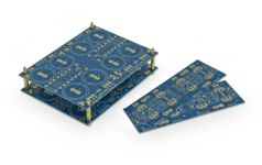
Found this image (attached) on the DIYAudiostore Uinversale PSU V3 product page - the part that has the rectifier diodes can be separated - maybe can make your placement a little easier.
You can also mount the transformers side ways using a bracket like illustrated by 6L6 in one of his build guides.
Attachments
Last edited:
Zmano1 ,
I'm building the USSA 3.2 amp , so will be building a mono CLrRC power supply , using one V3 board .
Will post photos , and the algebra to calculate the value of the damping Resistor , when I get the chance .
If you are building the USSA 5 amp , IMO dual CRC power supplies looks to be ideal .
For the USSA 5 amp , the jFET's set up a CCS ( Constant Current Source ) .
https://www.vishay.com/docs/70596/70596.pdf
Then FAB has crisscrossed the CCS's on the power supply rails .
As such , I suspect the PSRR ( Power Supply Rejection Ratio ) for the USSA 5 is probably very good , allowing a CRC power supplies .
So I suggest Project16 CRC power supply boards for the USSA 5 .
However , if you are set on going with the V3 boards , highly recommend making a 1/2 scale drawing
to make sure everything can be squeezed in the case .
.
Zman01 ,
Note , the V3 board requires a specific pin out for the power diodes . Common cathode diodes ( pin 2 )
and the tracts on the board connect the 2 anodes ( pins 1 and 3 ) .
Not getting into a heated debate about diodes ( PN junctions ) , I searched for some pin for pin compatible diodes , with a TO - 247AC case
and here are some considerations .
VS-60CPU06-N3 .... 2 x 30 Amp .... 600 v .... 1.1 Vdc .... 110 nC ..... $33.5 Cdn for 10
VS-60APH03-N3 .......... 60 Amp .... 300 v .... 0.85 Vdc ..... 65 nC ..... $54.80 Cdn for 10
VS-MUR3020WT .... 2 x 20 Amp .... 200 v .... 0.85 Vdc ..... 19 nC ..... $78.20 Cdn for 10
VS-60APH03-N3 is possibly a best value diode .
https://www.vishay.com/docs/94796/vs-60aph03-n3.pdf
Also , notice on the datasheet of the VS-60APH03-N3 it shows that the back of the case is NOT connected to the diodes .
This being said , many DIY audio builders are switching ( no pun intended ) to using LT4320 diode bridge controllers
to switch power MOSFET's . But boards will be needed for these .
Also , if it makes any difference , note how project16's board's can accommodate up to 40 mm caps ,
while 35 mm caps is the max for the V3 board .
There is also one trick Project16 has used . See how it uses only 1 diode bridge . This should help the + Ve and - Ve voltage rails
to have the same voltage magnitude .
In theory , if the noise and ripple , on both voltage rails , are equal , but opposite in phase , then this should cancel out at Vout , when the Vout = 0 Vdc .
HFA15PB60-n3 diodes could be a consideration for Project16 's boards .
https://www.vishay.com/docs/94052/vs-hfa15pb6.pdf
.
For Class A builds, skip the silicon BR’s and go for LT4320 active rectification.
Prasi has a GB currently going on with LT4320 ideal bridge and CRC on a single board.
https://www.diyaudio.com/community/threads/lt4320-based-active-rectifier.336572/page-76
Prasi has a GB currently going on with LT4320 ideal bridge and CRC on a single board.
https://www.diyaudio.com/community/threads/lt4320-based-active-rectifier.336572/page-76

Vunce ,
Thanks for pointing us in the right direction . The USSA 5 probably has a really good PSRR , but even with that ,
IMO its still important have ultra quiet supply rails .
Recall , there is the leakage inductance of the transformer , and this inductance stores energy in a magnetic field ,
when the the diodes switch off fast , this creates a v(t) = - L di / dt spike .
With a Bridge Rectifier , looking at traces of a well tuned snubber , the overshoot and ringing are mostly gone , and the switching spike has been reduced
but some of the spike is still there .... Which will put a noise spectrum on the supply rails .
https://www.diyaudio.com/community/...bber-using-quasimodo-test-jig.243100/page-122
I've looked and looked , but there is almost nothing out there showing scope traces or simulations ,
showing LT4320 controllers reducing switching noise .
Except , DIYAudio member nattawa took a LT4320 controller , and used it to control a diode bridge ( not MOSFET's ) .
https://www.diyaudio.com/community/...l-bridges-they-are-cool-and-quiet-too.351849/
.
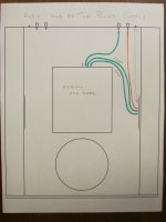
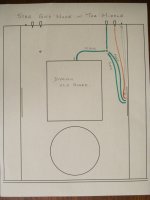
So here is the set up for the Analog GND that I am proposing - any recommendations would be appreciated
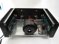
The L and R channel each have their own Star GND node - the location is shown in the photo attached .
I'm intending on using a threaded rod and ring terminals for this
To each Star GND node - Speaker GND , Power Supply GND , Amplifier PGND and GND are connected
Use either 12 awg or 10 awg cable for this .
Dumb Question # 47 , How should the RCA ground be set up ?
Note
- the transformer shown is for the display only , and soon to be replaced with an AnTek AN - 6218 .
- the connection tabs for the USSA amp are at the bottom , speaker binding posts are at the bottom
- following a post here , the USSA Amp is centered in the heat sink
Attachments
Concerning the star GND note .
The GND on the power supply is usually considered the quietest location , so one train of thought is set up the analog star GND node there .
Experienced designers on this website have argued " its an Amplifier " , so a star GND node should be set up on each Amp board .
But if you examine NP's F5 , you'll see he has set up a L and R star GND node 1/2 way between the Amp ,
Power Supply , RCA GND and Speaker GND .
With preamps I've built , the eyelets of the RCA GND's are all wired together , then 1 wire goes off to the star GND node .
The RCA shield / GND does not actually get connected directly to the preamp board .
But , FAB has set up GC - a low current GND , for the voltage gain section , so it looks like the RCA shield / GND
goes straight to the USSA 5 board .
.
Uunderhill
For clarification, on the USSA PCB V 0.4 you need to connect both the GND and PGND to the main power supply GND. GC is The input/feedback ground. This is where you need to connect the RCA GND.
Fab
For clarification, on the USSA PCB V 0.4 you need to connect both the GND and PGND to the main power supply GND. GC is The input/feedback ground. This is where you need to connect the RCA GND.
Fab
Fab ,
The Exicon MOSFET's have arrived and the AnTek AN - 6218 transformer has arrived .
I just need a few more bits and the 6061 Architectural " tubing" for the heat sinks .
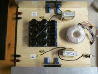
The issue is if the speaker Gnd , Amp Gnd and PGnd , for both the L and R channel are all connect to the mono power supply board ,
then six 0.25 " disconnect tabs will be required for the Gnd Connections - as shown below .
However , with the DiyAudio Stores V3.0 power supply board , for the Gnd , there are solder islands set up for two 0.25 " disconnects.
But I could , file the disconnects , and change the jumpers , to get 4 more disconnects on the board .
To set up the Gnds as you've described , I'll try to get 4 more 0.25 " disconnects attached to the board ,
if not , I'll have to go with plan B - having the Star Gnd node in the middle .
.
The Exicon MOSFET's have arrived and the AnTek AN - 6218 transformer has arrived .
I just need a few more bits and the 6061 Architectural " tubing" for the heat sinks .
The issue is if the speaker Gnd , Amp Gnd and PGnd , for both the L and R channel are all connect to the mono power supply board ,
then six 0.25 " disconnect tabs will be required for the Gnd Connections - as shown below .
However , with the DiyAudio Stores V3.0 power supply board , for the Gnd , there are solder islands set up for two 0.25 " disconnects.
But I could , file the disconnects , and change the jumpers , to get 4 more disconnects on the board .
To set up the Gnds as you've described , I'll try to get 4 more 0.25 " disconnects attached to the board ,
if not , I'll have to go with plan B - having the Star Gnd node in the middle .
.
Attachments
Hi Underhill
you are better running dual mono using 2 independent supplies, it prevents so much possible issues….
I am not aware if some builders have used only one PSU in this project…
Anyway star ground at power supply node gives very good results.
if you have no choice you can bridge the GND and PGND at the amplifier board level And still have star ground at PSU. It will work well but just differently for AC power line remaining noise figure.
Fab
Last edited:
Yes , as I realize now , there are lots of advantages of running dual mono power supplies .
But ... a CRC power supply filter , is just a 1 single pole power LPF .
This is probably why builders are reporting that LT4320 power diode boards , and those SLB ( Smooth Like Butter )
capacitance multiplier boards , are making an improvement .
With the mono power supply board , I'm planning on adding Hammond 159ZL chokes
These have an inductance of 2.5 mH with r = 0.044 and have a 10 Amp rating .
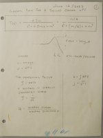
Simulation software shows the roll off of a CLrRC filter is - 40 dB / decade .
So that's saying its 2 pole LPF , so I brushed the dust off my 40 year math notes , *
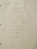
and here is transfer function and algebra , showing how to calculate the value of R required to dampen the choke .
I'm pretty sure this is correct , because it matches with other people's measurements and simulations .
Recall , in an ideally dampened system Zeta = 0.707 , but some people have set Zeta as low as 0.5
Looking from the supply rails into the Amp , the supply rails would see a CCS .
In perfect world a CCS has an infinite impedance , so an amp does not affect the damping .
However , note how the equation shows the second set of caps does affect the dampening .
.
.
* Please note : while you and Ggetzoff were off at the Pub having a few beers , and getting A's in math ,
I was working my tail feathers off just to gets C's .
.
- No cross talk between channels
- the power supply caps boards can be mounted right close to the amp board - allowing very short power cable lengths
- and there are far more manufactures who make 250 VA to 300 VA transformers , with dual 18 Vac + 18 Vac secondaries .
But ... a CRC power supply filter , is just a 1 single pole power LPF .
This is probably why builders are reporting that LT4320 power diode boards , and those SLB ( Smooth Like Butter )
capacitance multiplier boards , are making an improvement .
With the mono power supply board , I'm planning on adding Hammond 159ZL chokes
These have an inductance of 2.5 mH with r = 0.044 and have a 10 Amp rating .
Simulation software shows the roll off of a CLrRC filter is - 40 dB / decade .
So that's saying its 2 pole LPF , so I brushed the dust off my 40 year math notes , *
and here is transfer function and algebra , showing how to calculate the value of R required to dampen the choke .
I'm pretty sure this is correct , because it matches with other people's measurements and simulations .
Recall , in an ideally dampened system Zeta = 0.707 , but some people have set Zeta as low as 0.5
Looking from the supply rails into the Amp , the supply rails would see a CCS .
In perfect world a CCS has an infinite impedance , so an amp does not affect the damping .
However , note how the equation shows the second set of caps does affect the dampening .
.
.
* Please note : while you and Ggetzoff were off at the Pub having a few beers , and getting A's in math ,
I was working my tail feathers off just to gets C's .
.
Attachments

haha….I went to the Pub after the math exam to empty my head 😉
Well last time I had to work with Laplace transforms was in school almost 30 years ago…🙄
Of course a better power supply should bring amplifier sound benefit but also depends on the overall system to hear significant differences…
you can also still have a better filtered supply for each channel (if you have enough room in your chassis….)
you can also try first the simple filter like second order filter and then afterwards the higher order one, it is fun to appreciate the effect of the change …😎
the number of reactive components gives the filter order.
Fab
Last edited:
Fab ,
Heat sinks are needed - I was going to buy a 32 " length of 2.0 x 4.0 " of 6061 T6 architectural tubing
and cut it with a chop saw for the heat sinks . But as it turns out , it won't have the surface area needed .
I know next to nothing about heat sinks , so hopefully this is correct
So than means a heat sink with a 0.5oC / Watt rating is needed for each channel ,
but there will probably be a bit more thermal resistance , so say 0.38oC / W ???
After a big hunt for heat sinks , I found
Multicomp
MP008442 is rated at 0.42oC / Watt
MP008443 is rated at 0.36oC / Watt
https://canada.newark.com/multicomp-pro/mp008442/heat-sink-alum-alloy-0-42-deg/dp/73AJ8862
Note how its got a 10 mm back plate which is plenty thick enough for threading into from the top and sides .
Mouser carries Wakefield thermally extruded heat sinks
https://www.mouser.ca/datasheet/2/433/Wakefield_Thermal_Extrusion_Profile_Guide-3050300.pdf
WKV 125469 is 12.75 " x 2.25 " x 12 " , with a rating of 0.56oC / W / 3 " .................................... pg 64
but cutting a block of heat sink material , on a table saw , perpendicular to the fins , is something I would advise against .
A machine shop would probably cut it with a band saw , but then it would need a bit of finishing .
So buying a block is out .
Another option is to buy
WKV 125373 , which is 4.375 " x 1.29 " x 12 " , with a rating of 1.4oC / W / 3" ............ .............. pg 60
So a 12 " length would have a rating of 0.35oC / W
but .... the fins would be horizontal
They are $43 Cdn each and 47 can ship immediately .
https://www.mouser.ca/ProductDetail/Wakefield-Vette/125373?qs=2WXlatMagcF/s/dajEtAVQ==
Turns out an order from mouser over $100 Cdn and shipping is free , so if a few other bits were put in with the order , shipping would be gratis .
As heat rises , vertical fins would probably be better , but any serious objections to horizontal fins ?
.
Heat sinks are needed - I was going to buy a 32 " length of 2.0 x 4.0 " of 6061 T6 architectural tubing
and cut it with a chop saw for the heat sinks . But as it turns out , it won't have the surface area needed .
I know next to nothing about heat sinks , so hopefully this is correct
- power supply with +/- 24 Vdc rails
- the MOSFETs biased at 1.2 Amps
- so one channel would be dissipating 58 Watts .
So than means a heat sink with a 0.5oC / Watt rating is needed for each channel ,
but there will probably be a bit more thermal resistance , so say 0.38oC / W ???
After a big hunt for heat sinks , I found
Multicomp
MP008442 is rated at 0.42oC / Watt
MP008443 is rated at 0.36oC / Watt
https://canada.newark.com/multicomp-pro/mp008442/heat-sink-alum-alloy-0-42-deg/dp/73AJ8862
Note how its got a 10 mm back plate which is plenty thick enough for threading into from the top and sides .
Mouser carries Wakefield thermally extruded heat sinks
https://www.mouser.ca/datasheet/2/433/Wakefield_Thermal_Extrusion_Profile_Guide-3050300.pdf
WKV 125469 is 12.75 " x 2.25 " x 12 " , with a rating of 0.56oC / W / 3 " .................................... pg 64
but cutting a block of heat sink material , on a table saw , perpendicular to the fins , is something I would advise against .
A machine shop would probably cut it with a band saw , but then it would need a bit of finishing .
So buying a block is out .
Another option is to buy
WKV 125373 , which is 4.375 " x 1.29 " x 12 " , with a rating of 1.4oC / W / 3" ............ .............. pg 60
So a 12 " length would have a rating of 0.35oC / W
but .... the fins would be horizontal
They are $43 Cdn each and 47 can ship immediately .
https://www.mouser.ca/ProductDetail/Wakefield-Vette/125373?qs=2WXlatMagcF/s/dajEtAVQ==
Turns out an order from mouser over $100 Cdn and shipping is free , so if a few other bits were put in with the order , shipping would be gratis .
As heat rises , vertical fins would probably be better , but any serious objections to horizontal fins ?
.
Last edited:
Look up the numbers for fin orientation. Probably wakefield or Avid might have that, I know wakefield used to.As heat rises , vertical fins would probably be better , but any serious objections to horizontal fins ?
These numbers are for free airflow, so they won't be as good on a shelf either. So watch your numbers because later you may put that amp in a shelf where airflow is even more restricted and the ambient temperatures are going to be higher. Lot's of head room.
Your heatsink temps may also be your internal case temperature, or it may be (probably) higher still. So you have to think of what goes on inside your chassis. 50° might be fine for the outputs, but what about the small signal parts and power supply? Just to throw this out there, failure rate doubles for ever 10 °C rise in temperature. This is true of all electronics and is a physics thing.
Anatech ,
Thanks for the coaching . After briefing looking into this , the design of heat sinks is an entire subject of study .
No doubt the inside of the case needs to have good ventilation , otherwise the case will be an easy bake oven .
This article compares vertical to horizontal fin orientation , when there is natural air flow .
http://www.thermalsoftware.com/vert_vs_horz_sink.pdf
Figure 5-15 shows a graph that plots Watts dissipated vs fin length ( mounted horizontally and vertically ) .
So using heat sinks with horizontal fins is out .
.
Last edited:
- Home
- Amplifiers
- Solid State
- USSA-5 Build with Review