It's possible, but you will need 2x2200uF eletrolytic capacitors to achieve non polarized 1.1mF
I don't have problems with electrolytics, but people, in general, don't like them much.
You'll need also an additional big inductor, but you can use smaller gauge and incorporate part of the 4.7 ohm resistance to the inductor winding, making it smaller and cheaper. I do that with mid-range/tweeter notch filters when I need them.
For sure, it's just an example that it's about circuit impedance. Would be silly to use current amp and then negate it with big passive parts. One could use voltage amp and use series impedance for similar outcome, low impedance for electrical damping at resonance and then increase it with frequency with a coil in series. Not as high impedance but could still reduce motor distortion some. So, kinda utilizing best of both "voltage drive" and "current drive".
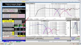
This is to 20 degrees off axis. Black line is on axis. I entered in approxamations for the inductor DCRs and this includes the driver offsets.My camera resolution, and hand writing lead you astray. That should be a .5mH coil on the mid, not a 5mH. The dot blended into the tail of the number 5. I didn't notice it looked that way initially. I later saw it, but figured you would catch it.
Start with about 20 degrees off axis, and then go about ten degrees each way, The variation is not bad, using the 7 degree frd files. So 7 degrees to about 30 degrees is a listening window. .The direction probably matters a lot, but I couldn't tell which way my software was indicating.
Attachments

Have you bought from US Coils before?For lowest dcr but higher inductance coils use this: https://uscoils.us/product/ussq55-12-3300/
I have gone through their website a couple times and the most I see of anything is them having only 1 in stock. Everything else is "available on backorder"
Did you try 20 degrees the other direction?This is to 20 degrees off axis. Black line is on axis. I entered in approxamations for the inductor DCRs and this includes the driver offsets.
This is to 20 degrees off axis. Black line is on axis.
I have tried this filter with 0 deg files of yours. Would you check it out?

Well, that is not the magical crossover, but only additional LCR series circuit to compensate the woofer impedance rise at the resonant frequency ("conjugate loading" by KEF, many years ago).Here is the magic crossover, it makes low impedance path between driver terminals enabling some electrical feedback.
Sorry, but 1.1 mF (!!!) condenser, 3.9 mH inductor and 50W resistor are very expensive addition to the crossover, only to make current drive usable! Besides, you didn't post the crossover schematic (as asked!), because current drive will mess up the frequency response of crossovers posted here before.
Last edited:
Yes, it is silly to use current amp with 99.999999% of all woofers on the market.Would be silly to use current amp and then negate it with big passive parts.
I have nothing against current drive, but there are no woofers today optimized for current drive.
Last edited:
Expensive juggling with additional components and unnecessary wasting amp power on series resistor, for a questionable improvement on distortion.One could use voltage amp and use series impedance for similar outcome, low impedance for electrical damping at resonance and then increase it with frequency with a coil in series. Not as high impedance but could still reduce motor distortion some.
The only logical and economically justified solution is amplifier with complex negative feedback to make it to have low output impedance at low frequencies and high output impedance at mid and high frequencies. But that knowledge is out of ability of 99.999% of all DIY folks.
I don't know for sure why there is a difference. Here's from minus 3 degrees to plus 25 degrees. If anything, I would suspect that the mid drops a dB or two at 2k, and twenty five degrees. The flattest response was around 14 degrees, I think. I've also made minor changes, but they are insignificant to the results you showed. Black line is 26 degrees, and the gray line is minus 3 degrees.
My Z offsets are set to zero. Are yours?
My Z offsets are set to zero. Are yours?
Attachments
Last edited:
I think most people assume cored inductors are ok as long as you don't drive them into saturation, but that's not the whole story. Every cored inductor will impart its own flavor to the driver its in the circuit with, even if its not saturated. Its even more audible with low sensitivity drivers, as these will require more power for a given SPL, so the total percentage of distortion compared to clean audio signal goes up as a result.
Winding your own coils is much more economical than buying them pre-wound, especially those using larger guage wire.
Its ok to incorporate the series resistance of an LCR into the coil windings. There's a point however, when the DCR will cause coil heating in lower frequency LCRs used around woofers and midbass drivers when driven harder. This causes the LCR to shift its effective range. The reason is copper has a positive temp coefficient of 0.4%/deg C where the nichrome wire in the series resistor barely changes. A reasonable shift in temp is 20 deg C which ends up being an 8% shift.
It basically depends on your priorities, whether these mentioned factors are a potentially noticeable issue. If you're using very high end drivers, I would spend the extra money on better inductors and capacitors.
Also, the notion that passive crossovers are inferior to active ones isn't true. The downside to passive filters is series resistance and cost, but a significant benefit is their ability to dampen diaphragm motion and back EMF at the origin. This can change the effective Q and mechanically dampen the diaphragm. Active filters can't do this. They can only modify the driven signal itself. Having control over the diaphragm can increase power handling and lower distortion. It also doesn't add noise like additional active filter stages can.

Yup. When you taken final measurements when using this program are you getting accurate results?My Z offsets are set to zero. Are yours?
VituixCAD is eerily accurate.
Yes, there are hysteresis and the non linear BxH curve from 0 to something below the saturation point.Every cored inductor will impart its own flavor to the driver its in the circuit with, even if its not saturated.
The point is how much.
From the measurements I did once, in a air gaped iron core (uR~10), I found harmonics lower than 48dB which was the limit of my 8-bit scope.
If you have woofers with THD around or below 48dB, which is quite low, then the option for air core is relevant.
Yes, iron core and incorporated resistance must be engineered.There's a point however, when the DCR will cause coil heating in lower frequency LCRs used around woofers and midbass drivers when driven harder.
Air core and super heavy and expensive high gauge inductor don't need much engineering.
I am not sure what I would call these drivers. They have crazy low distortion numbers but they are difficult (understatement) to use.It basically depends on your priorities, whether these mentioned factors are a potentially noticeable issue. If you're using very high end drivers, I would spend the extra money on better inductors and capacitors.
The woofer is the Epique 5.5"
The mid the 8" GRS planar mid/tweeter
The tweeter is the GRS RT1R ribbon tweeter.
I am trying to make this work. Taming these is like taming someone else's badly raised children.
I've seen it does add distortion even at 1w. These will likely be played at a handful of watts as they will be 1 meter from my head and I'll be working while listening to them. Pretty hard to review engineering designs/schematics with music blasting.I think most people assume cored inductors are ok as long as you don't drive them into saturation, but that's not the whole story. Every cored inductor will impart its own flavor to the driver its in the circuit with, even if its not saturated. Its even more audible with low sensitivity drivers, as these will require more power for a given SPL, so the total percentage of distortion compared to clean audio signal goes up as a result.
The woofer is pretty low sensitivity. Even I remember correctly it is 86DB. Not horrible, but not the greatest. Where it shines is distortion. Very low. A little under 1% for its entire frequency range. I picked them up for $74 a piece so I can't really complain
What is the red line supposed to show? What data needs to be input for that? All the speaker angles?The bad part of unknown measurement type is that here we cannot see the whole picture. That red line on directivity graph should show meaningful and important data, but it does not. I can guess, that at the crossover point of tweeter here we can see some problem, but from 40 degrees of data it is hard to tell.
For some us more nerdy types, this is the fun. I deal with high level overview of engineering designs all day, every day. I don't often get the chance to go into the nitty gritty of a design and perfect it. R&D costs money, there are deadlines, I have other projects that are coming in, etc.Same for most of us, but this is "over my head".
How in hell can you discuss coils as a problem in general?
No offence, but more fun with building and combinations of drivers.
With this I get to take my time and run through every detail, perfecting it to my liking. Spend any time at an engineering firm and you'll also find how much of a luxury this truly is.
You tell me. Does this woofer qualify?If you have woofers with THD around or below 48dB, which is quite low, then the option for air core is relevant.
Attachments
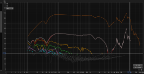
Hi, I didn't get the legend, but I suppose the white line is THD, right?
If yes, THD is in between -35 and -40dB, so I don't think it's worth to use an air core.
I like to engineer the components to squeeze them, knowing the limits and the effects, rather than just use an expensive solution, where no engineering is need.
If you go for an off the shelf iron core, just make sure it handles the maximum peak current you need (peak of sine wave, so maximum current in time domain).
I would build a cheap iron core (or buy an entry level one), with enough cross area, and measure THD with and without it at several levels (low, medium and high SPL). Just keep uR<10 (relative permeability) - this is 10x gain so you still save a lot of cooper and keep DCR low.
If you see relevant difference, then go for an air core and measure THD again to compare, cause inserting a filter changes the behaviour.
That's what I did for some speaker I've built.
If you see relevant difference, then go for an air core and measure THD again to compare, cause inserting a filter changes the behaviour.
That's what I did for some speaker I've built.
Last edited:
- Home
- Loudspeakers
- Multi-Way
- Air Core vs Iron Core - Sensitivity