Actually I have not encountered a mains over voltage. More often under voltage like Tony described.
I have examples of caps like those that are in good condition after nearly 50 years.
Wish I was in as good condition as I was 50 years ago. I'd take even 20.

Would have been nice to see those silver electrolytics on the RP-3 board go in the trash bin. I have replaced hundreds of those exact parts over many years on the legacy railroad equipment I service at work. If they are older than ten years, I just replace them. The equipment may still "work", but I've seen some strange intermittent operation and sporadic failures as those caps are on the way out...
Hello Mr. Lim,Dear H,
Glad you found my post useful. I learned a lot over the years through forums like this. So I wanted to share my experience so others can learn from it too.
The protection circuit monitors the following :
1. excessive DC offset at the amp output
2. Over temperature.
3. Over current / short circuit
4. Unregulated power rail over voltage
5. Regulated power rail over voltage
My guess is that it could be fault no 4. 1,2 and 3 are unlikely as both amps always behave likewise at the same time. As for no 5, once voltage regulator fails it will always fail and not recover on both channels at the same time.
You are from UK? Mains is 240V ? The unregulated voltage rails will fluctuate with the mains. Check your voltage selector setting. Could it be set like 220 or 230V instead of 240v?
I was thinking there may be a component failure on the protection board just like the SCR in my case but your amp failure symptom of both working and failing at the same time suggest same fault at the same instant which may point to environment like temp and line voltage. Unlikely to be temperature as it is also unlikely that two thermal switches fail at the same time.
I call this kind of fault finding as looking for gremlins. Makes very little sense.
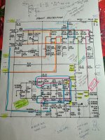
Of course there is always the brute force approach. Eliminate one fault at a time even though it may feel unlikely to be the cause like I did on the protection board.
Take a look at me post with the highly marked out protection board circuit and go from there.
Good luck 😊
Thank you for your detailed answer.
It makes perfect sense that it may be the AC voltage of the house. The ML20.6 monoblocks were moved from an Asian city supplying around 220V (+/- 2%) and the back of the amp marked 210V - 240V. The ML20.6 is now in the UK and plugged in to AC mains with voltage about 242V (average). I measured this with a Fluke 87V multimeter. The back of ML20.6 shows that it can be rewired to suit 230V - 250V AC. It seems that this should be a better match for UK house AC voltage. I'll try to rewire ML20.6's transformer jumpers to change the input voltage acceptance and see if it can fix the issue. The rewiring is much more difficult than most other vintage amps from Japan or USA.
Last edited:
Hello Mr. Lim,
Thank you for your detailed answer.
It makes perfect sense that it may be the AC voltage of the house. The ML20.6 monoblocks were moved from an Asian city supplying around 220V (+/- 2%) and the back of the amp marked 210V - 240V. The ML20.6 is now in the UK and plugged in to AC mains with voltage about 242V (average). I measured this with a Fluke 87V multimeter. The back of ML20.6 shows that it can be rewired to suit 230V - 250V AC. It seems that this should be a better match for UK house AC voltage. I'll try to rewire ML20.6's transformer jumpers to change the input voltage acceptance and see if it can fix the issue. The rewiring is much more difficult than most other vintage amps from Japan or USA.
Do they sell transformers in the UK to bring down the 240 to 220? In the US stuff that goes from 120 to 100 is quite common. The guys who collect Japanese Audio all have them.
It might be better than ripping into the amp.
https://www.larsonelectronics.com/p...MI58SD0IT5igMVkidECB0aWAt-EAQYASABEgK6zPD_BwE
At worst just get some big Variacs.
I’m sorry that I missed this thread until now.Good luck.
I went the same road many years ago before any schematic was available, on the Internet.
So, I had to do a complete re-engineering taking several weeks.
The biggest problem with my 20.6 was that the AP5 boards were made from Teflon.
This material behaves like chewing gum, leading to broken traces and island at least once a year.
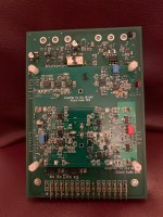
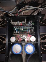
Although ML came with a very expensive replacement with different PCB material called Arlon, I went my own way and designed a completely different more modern amplifier board.
I haven’t had any problem since then.
Hans
Attachments
Wow! That’s incredible work with modern SMD. WELL DONE! Do SMD make any audible differences?
Luckily, the amp I worked on, the AP3 had no problem. Not sure if it is teflon or Arion. The one I worked with was a bit greyish colour. I knew it wasn’t the normal FR board material.
What was your amp fail mode?
Luckily, the amp I worked on, the AP3 had no problem. Not sure if it is teflon or Arion. The one I worked with was a bit greyish colour. I knew it wasn’t the normal FR board material.
What was your amp fail mode?
A cheaper option and better approach is to change the zener voltage. That way no sacrifice of sound quality. Variac or additional transformer in the power path will increase power lines impedance.Do they sell transformers in the UK to bring down the 240 to 220? In the US stuff that goes from 120 to 100 is quite common. The guys who collect Japanese Audio all have them.
It might be better than ripping into the amp.
https://www.larsonelectronics.com/p...MI58SD0IT5igMVkidECB0aWAt-EAQYASABEgK6zPD_BwE
At worst just get some big Variacs.
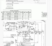
Oh. Scratched that. Easier to increase R201 and R203. Scaled it accordingly. If you are measuring 245V vs 240V which is only about 2%. To be safe to prevent false triggering, up the value by 5% should be ok. Will only increase power dissipation a little at the voltage regulator without triggering the protection.
Attachments
Fail mode as mentioned was the Teflon material that wasn't a solid base for a PCB, that's why it was later replaced by Arlon.Wow! That’s incredible work with modern SMD. WELL DONE! Do SMD make any audible differences?
Luckily, the amp I worked on, the AP3 had no problem. Not sure if it is teflon or Arion. The one I worked with was a bit greyish colour. I knew it wasn’t the normal FR board material.
What was your amp fail mode?
But looking at the pictures that you posted, they are also Teflon.
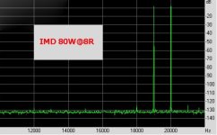
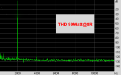
And I did not translate the ML design into a SMD design, but created a new design where the transfer function is completely determined by the linear phase filter and not by the load, while still using the original external output stage working up to 100Watt in class A.
Does it sound different ?
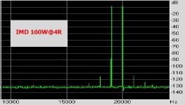
Yes it does, at least to my ears it's a real step beyond the original ML20.6
Attached are a images to show the very low measured distortion figures.
Hans
Attachments
I was thinking also. Perhaps the zener diodes may have drifted to lower voltages which may cause the protection to kick in at actually good operating rail voltages. Remove and measure actual zener voltages on D201 and D203.Oh. Scratched that. Easier to increase R201 and R203. Scaled it accordingly. If you are measuring 245V vs 240V which is only about 2%. To be safe to prevent false triggering, up the value by 5% should be ok. Will only increase power dissipation a little at the voltage regulator without triggering the protection.
Worth measuring them.
Thank you Mr. Lim. This is also an alternative.Oh. Scratched that. Easier to increase R201 and R203. Scaled it accordingly. If you are measuring 245V vs 240V which is only about 2%. To be safe to prevent false triggering, up the value by 5% should be ok. Will only increase power dissipation a little at the voltage regulator without triggering the protection.
Based on the schematics found on internet, the jumpers can be re-connected to suit the AC input voltage. In my case, it should be moved to a higher voltage.
Attachments
Hello Mr. Lim,Haha. It is sandwiched in between the two boards and it is way inside.
I would need a long plastic screwdriver to reach there and at the same time not to short any other part of the circuit while doing so.
Kung Hei Fat Choy!
Would you mind sharing the details of the following: -
(1) adjustment of bias: there's no guideline about bias adjustment in theML20.6 schematic found on internet. What figure did you aim at adjusting the bias? Where is or are the potentiometer(s) for adjusting bias?
(2) adjustment of speaker output DC offset: you mentioned the pots in your article but you also said that there were more than one pots that changed the DC offset figure. Usually in power amp, there's only one pot per channel for adjusting the DC offset based on my limited knowledge. Could you elaborate how to adjust the DC offset for ML20.6 each channel (each monoblock amp) in case there are more than one pot?
(3) You had taken apart the heatsink modules which had Motorola TO3 output transistors on them. I remember in a past article somewhere on internet, a ML20.6 owner said that once the heatsink modules near the speaker output terminals were removed, be prepared to replace the mica insulator. I am not sure what he meant ----- did he mean taking the opportunity to replace the age old TO3 mica insulator or taking apart heatsink modules will damage the mica insulator?
Thank you.
Hello Hans,I’m sorry that I missed this thread until now.
I went the same road many years ago before any schematic was available, on the Internet.
So, I had to do a complete re-engineering taking several weeks.
The biggest problem with my 20.6 was that the AP5 boards were made from Teflon.
This material behaves like chewing gum, leading to broken traces and island at least once a year.
Although ML came with a very expensive replacement with different PCB material called Arlon, I went my own way and designed a completely different more modern amplifier board.
I haven’t had any problem since then.
Hans
DId you DIY a AP5 card by yourself? That's really difficult, if not impossible, for a normal person to make such a sophisticated PCB to replace the original one. Is there any expert who sells similar product (card) to help the ML20.6 owners? My monoblocks do not have the problem yet but may be years later there will be such a problem.
Adjust this pot first. Connect a voltmeter to the output terminal. The DC offset should respond to this pot adjustment. If you can’t get it near to zero DC volt, then you will need to adjust the other pot sandwiched between the two boards. You need to be careful adjusting the second pot. You will require an insulated long screwdriver for this. See my photo to locate the second pot.Hello Mr. Lim,
Kung Hei Fat Choy!
Would you mind sharing the details of the following: -
(1) adjustment of bias: there's no guideline about bias adjustment in theML20.6 schematic found on internet. What figure did you aim at adjusting the bias? Where is or are the potentiometer(s) for adjusting bias?
(2) adjustment of speaker output DC offset: you mentioned the pots in your article but you also said that there were more than one pots that changed the DC offset figure. Usually in power amp, there's only one pot per channel for adjusting the DC offset based on my limited knowledge. Could you elaborate how to adjust the DC offset for ML20.6 each channel (each monoblock amp) in case there are more than one pot?
(3) You had taken apart the heatsink modules which had Motorola TO3 output transistors on them. I remember in a past article somewhere on internet, a ML20.6 owner said that once the heatsink modules near the speaker output terminals were removed, be prepared to replace the mica insulator. I am not sure what he meant ----- did he mean taking the opportunity to replace the age old TO3 mica insulator or taking apart heatsink modules will damage the mica insulator?
Thank you.
when you remove the power transistors from the heatsink, you can still reuse the mica sheet if they are not damaged. It’s easy to wipe off the old heat grease and get further cleaning with alcohol solvent. Reapply heat compound and mount back. Mica sheet does not degrade over time and can be reused.
Attachments
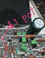
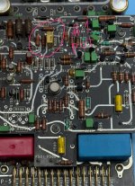
So it's the yellow pot that is for adjusting the DC offset! Cheers.Adjust this pot first. Connect a voltmeter to the output terminal. The DC offset should respond to this pot adjustment. If you can’t get it near to zero DC volt, then you will need to adjust the other pot sandwiched between the two boards. You need to be careful adjusting the second pot. You will require an insulated long screwdriver for this. See my photo to locate the second pot.
when you remove the power transistors from the heatsink, you can still reuse the mica sheet if they are not damaged. It’s easy to wipe off the old heat grease and get further cleaning with alcohol solvent. Reapply heat compound and mount back. Mica sheet does not degrade over time and can be reused.
By the way, do I need to re-adjust the bias in case I replace some electrolytic capacitors in the ML20.6? I intend to replace most of them, some on motherboard, some on AP3 card and some on AP5 card.
I'm just a normal person who was angry to be left in the dark by ML. All the local ML dealer offered was to replace my teflon boards by Arlon boards for a ridiculous price of 4000,- Euro per per board, so in total 8000,- Euro., which I did not accept.Hello Hans,
DId you DIY a AP5 card by yourself? That's really difficult, if not impossible, for a normal person to make such a sophisticated PCB to replace the original one. Is there any expert who sells similar product (card) to help the ML20.6 owners? My monoblocks do not have the problem yet but may be years later there will be such a problem.
Lot's of time went into the reverse engineering, since no circuit diagram in any form was available at that time.
But to be fair I'm a MsCEE, so it was possible for me to unravel all details.
Hans
- Home
- Amplifiers
- Solid State
- Mark Levinson No. 20.6 Repair