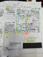
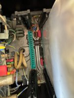
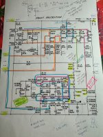
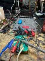
Now back to the protection circuit. Attached is a picture of the protection circuit with all my scribbling trying to figure out what is tripping the protection even though the rest of the modules have been removed.
From what I figured out was the followings were being monitored for faults
1. Amplifier output for excessive DC
2. Output short circuit
3. Unregulated power rails : over voltage
4. Regulated power rail: : over voltage
5. Over temperature : overheat
I guessed that amplifier output related shouldn't be a problem since AP-5 and the other amplifier related heatsink modules were not installed.
It’s down to the power rails and thermal related.
I can rule out regulated power rails since I already tested on the bench that regulator is working.
As for raw unregulated supply rails it is very unlikely as the protection circuit is still triggering so there must be supply voltage.
So it’s down to the thermal fuses which were in the circuit to protect against overheating. These fuses are usually rated somewhere around 80C.
As the amp is tripping at cold start it is definitely not heat related so it could be faulty thermal fuses.
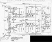
From the schematic there were three thermal fuses. Actually I should call them thermal switches. Connected in series to ground from the sensing point. If any of the switches open it will trigger the protection circuit.
Great ! Seems like this is very likely cause.
From what I figured out was the followings were being monitored for faults
1. Amplifier output for excessive DC
2. Output short circuit
3. Unregulated power rails : over voltage
4. Regulated power rail: : over voltage
5. Over temperature : overheat
I guessed that amplifier output related shouldn't be a problem since AP-5 and the other amplifier related heatsink modules were not installed.
It’s down to the power rails and thermal related.
I can rule out regulated power rails since I already tested on the bench that regulator is working.
As for raw unregulated supply rails it is very unlikely as the protection circuit is still triggering so there must be supply voltage.
So it’s down to the thermal fuses which were in the circuit to protect against overheating. These fuses are usually rated somewhere around 80C.
As the amp is tripping at cold start it is definitely not heat related so it could be faulty thermal fuses.
From the schematic there were three thermal fuses. Actually I should call them thermal switches. Connected in series to ground from the sensing point. If any of the switches open it will trigger the protection circuit.
Great ! Seems like this is very likely cause.
Attachments

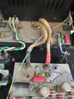
Let’s go look for the thermal switches and check them.
From the schematic is was not obvious where they are located. A good guess is that they are likely located on the heatsink.
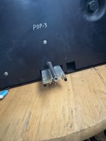
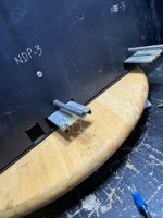
Found two of them. They were located on the NDP and PDP heatsink modules.
Ah hah! That explained why the amplifier tripped as these modules were not installed during the test.
With my step by step approach I didn’t want to simply attach these two modules and retest.
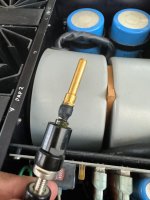
So in order to test I had to bypass this thermal switches by providing a path to ground at the sensing point.
A simple way is to short out the two points of the thermal switches to complete a path to ground.
From the schematic is was not obvious where they are located. A good guess is that they are likely located on the heatsink.
Found two of them. They were located on the NDP and PDP heatsink modules.
Ah hah! That explained why the amplifier tripped as these modules were not installed during the test.
With my step by step approach I didn’t want to simply attach these two modules and retest.
So in order to test I had to bypass this thermal switches by providing a path to ground at the sensing point.
A simple way is to short out the two points of the thermal switches to complete a path to ground.
Attachments
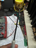
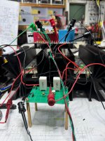
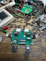
See photo. I wired two jumpers to simulate that the modules were inserted and that the thermal switches were in circuit.
Wah Lah! Power up and no trip ! 👏🏻👏🏻👏🏻
I took the step by step diagnosis a bit too far and wanted to test the other four modules independently to make sure they were working per their functions. I have tested them briefly earlier in a gross go no go test and there were no shorts.
I could have plugged back the remaining four modules and do a power up test but I didn’t and proceeded to test the other four modules independently just to be sure.
On hind sight it is quite low risk to plug in the modules and test.
I had to build a few test jig in order to test the other modules. I will skip this part as eventually they tested good for the functions they were meant to performed. I will
Add this part at the end of the story for people who may encounter problems with these modules and want to know how to test them independently.
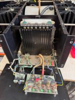
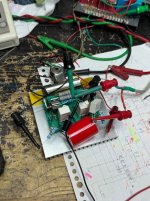
At this juncture I would like to explain the comment I made earlier in the story why I said this amplifier is not meant for field repair. The bias adjustment pot is way down on the motherboard which is inaccessible form the top to adjust with a screw driver. It is covered and blocked when the RP-3 and AP-5 boards were inserted.
See the third photo, the adjustment pot is circled in red. You will need an extender board for the AP-5 to keep it out of the way so you can adjust the bias pot.
Wah Lah! Power up and no trip ! 👏🏻👏🏻👏🏻
I took the step by step diagnosis a bit too far and wanted to test the other four modules independently to make sure they were working per their functions. I have tested them briefly earlier in a gross go no go test and there were no shorts.
I could have plugged back the remaining four modules and do a power up test but I didn’t and proceeded to test the other four modules independently just to be sure.
On hind sight it is quite low risk to plug in the modules and test.
I had to build a few test jig in order to test the other modules. I will skip this part as eventually they tested good for the functions they were meant to performed. I will
Add this part at the end of the story for people who may encounter problems with these modules and want to know how to test them independently.
At this juncture I would like to explain the comment I made earlier in the story why I said this amplifier is not meant for field repair. The bias adjustment pot is way down on the motherboard which is inaccessible form the top to adjust with a screw driver. It is covered and blocked when the RP-3 and AP-5 boards were inserted.
See the third photo, the adjustment pot is circled in red. You will need an extender board for the AP-5 to keep it out of the way so you can adjust the bias pot.
Attachments
Now back to the story. With the power up trip resolved. I could have inserted the rest of the modules and do the power up test but didn’t.
I spent several days building test jigs to test the other heatsink modules independently and confirmed that they worked.
Now to plug them in and do a full test.
Tadah! No trip. Great. Amplifier seemed to be powering up normally. First there was an inrush current llimit for a fraction of a second followed by full power.
The amp was drawing about 350W idle. Expected for a class A amp.
Proceeded to connect input and output and no sound. Alamak! (A local word for OMG 😨)
My initial fear was could it be damage to the motherboard caused by the dislodged heavy transformer.
Dismantled the back panel to check the input socket and binding post connections.
All connections tested good. With the input signal connected and amp powered on I measured the output signal on the inside output connecting wires there was signal.
Huh! 🤔
Attachments
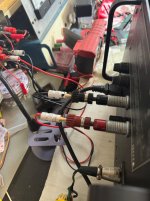
Turned out that the speaker cable connector provided by ML was defective.
You can’t plug your normal banana plug into the output sockets. You need this special adaptor.
Photo showed the customised adaptor, the broken one and the repaired.
After that we have lift off. Amp began singing.
Problem fixed and ready to close this chapter.
I always made it a point to run in a couple of days before returning to the owner.
After about an hour it tripped again.
Oh no!!!😢
Attachments

So what else can be triggering the protection circuit.
Couldn’t be over temp. I measured the heatsink temp and it was about 55C. Usually the thermal switches are rated around 80C or more.
How do I probe the trigger points to troubleshoot? It is not accessible when inserted. I would need an extender board to raise the RP-3 board up to probe the voltages. My point again not meant for field repair.
Somehow I have to figure out how to rule out each trigger mechanism.
Back to the drawing board and study the schematic further.
One approach is to add fly wires to each trigger node and monitor outside with the RP-3 inserted.
I believe that it is not a catastrophic fault as amp could play for about an hour before tripping and after a few minutes could be power up again
So I decided on the following approach. I shall defeat each trigger point and monitor if it still tripped.
Before I started down that road the First trigger which can be easily checked is output DC offset.
DC offset was 110mV although not small it shouldn’t be high enough to trigger a fault.
Nevertheless, this needed to be trimmed down. An obvious place to find the pot would be the AP-5 board.
Attachments
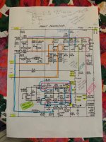
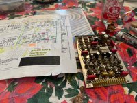
Photo shows the AP-5 board. It is a double decked PCB assembly. The top PCB shows one 10K pot. Fortunately this pot is easily accessible and I begin to tweak the pot. Each time I turned the pot to reduce the offset it came back again. For example I would make a turn and the offset will go down to 90mV and within a fraction of a second it went back to 110mV again. Appeared as though there is a DC servo that locked the DC offset to 110mV.
Oops!
Study the schematic showed that the input stage is super complicated. Apparently the two PCB each contain one side of a differential input amplifier. The top PCB is just for the inverting input of the differential amp. The bottom PCB is for the non inverting input.
So there may be another pot for adjusting the non inverting input.
Yes. You may be shocked next to see where it is located.
Attachments

Haha. It is sandwiched in between the two boards and it is way inside.
I would need a long plastic screwdriver to reach there and at the same time not to short any other part of the circuit while doing so.
I would need a long plastic screwdriver to reach there and at the same time not to short any other part of the circuit while doing so.
Attachments
Respect, what a pile of crap you have to deal with.😎
I managed to tuned the offset down to a few mV. I honestly didn’t expect this to be the trigger but of course still needs to be adjusted.
As expected without doing anything else it tripped again after power on for some time. It didn’t take the full 59 mins or so as the amp is still fairly warm.
Referring to the schematic again. I proceeded to eliminate the trigger mechanism. Actually this can be done faster.
By lifting off D222 diode I can defeat the following triggers: raw and regulated power rails, DC offset, thermal switches except the overcurrent.
Haha. It still tripped.
Removed the last trigger : over current. Still tripped. 🧐😱
Conclusion : the circuit is giving a false fault trigger.
Nothing can contribute to the triggering. The diac (D238) even though faulty (open or short) would not trigger the SCR. An SCR would need a positive voltage relative to cathode to trigger it. With all triggers removed this voltage will not receive any positive voltage. Boils down to the SCR itself. I probed the voltage between gate and anode during power up before triggering. It measured around a 100mV. It should be zero. This voltage slowly creeped up at it temp of the amp heats up and eventually triggers.
Haha. A bad SCR with a leaky gate terminal.
Removed and tested in on the bench. Confirmed faulty. Biased up the SCR and it triggered as I warmed it up with heat gun.
Usually I don’t work with SCR in the circuits I dealt with. Luckily I managed to find one in an old stash or parts in a box in my attic.
I found a 1972 date code Texas Instruments made SCR. ( Ray if you are reading this you will be smiling). By the way I worked at Texas Instruments Singapore for 36 years till
I retired. Was my first and only employer. 😊
Attachments

Of course I tested the 52 years old part and it is still functioning. Kudos to TI 😊
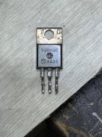
Photo shows the offending component. A 1992 Motorola device.
After replacing the faulty SCR there was no more false triggering.
The amp ran for several hours without tripping.
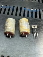
In summary, after almost a month of troubleshooting. Only three parts were replaced. One SCR (silicon controlled rectifier) and two capacitors.
IN CONCLUSION:
Original fault trigger was due to the two damaged capacitors. After replacing the capacitors the amp works and tripped after an hour of play. Second fail mechanism caused by a leaky SCR.
What a journey. Never cease to learn no matter how old a person is.
Photo shows the offending component. A 1992 Motorola device.
After replacing the faulty SCR there was no more false triggering.
The amp ran for several hours without tripping.
In summary, after almost a month of troubleshooting. Only three parts were replaced. One SCR (silicon controlled rectifier) and two capacitors.
IN CONCLUSION:
Original fault trigger was due to the two damaged capacitors. After replacing the capacitors the amp works and tripped after an hour of play. Second fail mechanism caused by a leaky SCR.
What a journey. Never cease to learn no matter how old a person is.
Attachments
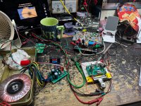
I will not post the part where I tested the other modules independently on the bench with jigs I designed. If anybody is interested just let me know.
I will attached a few pictures here. This process took more than a week to complete.
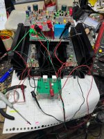
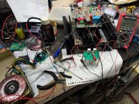
Photo show jig and test set up to test the output current biasing function
I will attached a few pictures here. This process took more than a week to complete.
Photo show jig and test set up to test the output current biasing function
Attachments
Thanks to all who followed this story. I thought it was interesting and a lot to be learned and worth sharing. 🥰
Thank you Mr Pass. Highly appreciated coming from the master himself. I am a big fan of yours.Congratulations on a good fix. Not a trivial effort.

Haha. Luckily this is my hobby and I am not doing this for a living. Otherwise I will starve to death.Respect, what a pile of crap you have to deal with.😎
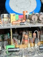
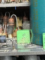
These two caps look like they came out of a war zone. 😉
Thanks for sharing this nightmare.
Thanks for sharing this nightmare.
- Home
- Amplifiers
- Solid State
- Mark Levinson No. 20.6 Repair