Yes. Both clockwise until they click. Turning them the opposite way the voltage increases.
When I get back home I’m going to pull the diodes and take a close look to see if I can read what they are. Might have grabbed some that weren’t in the right bin.
When I get back home I’m going to pull the diodes and take a close look to see if I can read what they are. Might have grabbed some that weren’t in the right bin.

Normally you would lower the effective R9 value only if you cannot increase bias to the desired level.
If your bias starts up high even if P1 is set to its maximum value then try removing the parallel 10K at R9.
If your bias starts up high even if P1 is set to its maximum value then try removing the parallel 10K at R9.
Last edited:
Dear Diyaudio community.
I need your help again.
I have now finished my second balanced monoblock and one of the circuit boards is behaving strangely.
After a cold start I can set both the quiescent current and the offset without any problems - everything is fine.
However, the offset then starts to rise as it heats up. After about 20 minutes it is then around 300mV, for example, and continues to rise.
After setting the offset to 0mV again it continues to rise, etc. - regardless of whether I connect the input to ground or not.
The quiescent current behaves completely normally and symmetrically as far as N and P are concerned.
After my inspection, all solder connections seems to be OK, all components are in the right place with the correct values.
Does anyone have any idea how I can get to the bottom of the problem and fix it?
Attached are pictures of the faulty circuit board.
Further up in the thread you can find pictures of the entire setup.


https://www.diyaudio.com/community/...ing-the-pass-f4-amplifier.234355/post-7728704
I need your help again.
I have now finished my second balanced monoblock and one of the circuit boards is behaving strangely.
After a cold start I can set both the quiescent current and the offset without any problems - everything is fine.
However, the offset then starts to rise as it heats up. After about 20 minutes it is then around 300mV, for example, and continues to rise.
After setting the offset to 0mV again it continues to rise, etc. - regardless of whether I connect the input to ground or not.
The quiescent current behaves completely normally and symmetrically as far as N and P are concerned.
After my inspection, all solder connections seems to be OK, all components are in the right place with the correct values.
Does anyone have any idea how I can get to the bottom of the problem and fix it?
Attached are pictures of the faulty circuit board.
Further up in the thread you can find pictures of the entire setup.
https://www.diyaudio.com/community/...ing-the-pass-f4-amplifier.234355/post-7728704
Last edited:
Are you talking about the offset or the bias?
I just dealt with this exact same issue but the bias kept rising (not offset) and forgot to post that I corrected the problem.
Put R9 back to 10k ohms and don’t parallel another 10k unless you absolutely need it.
The F4 I just finished had one channel where I had to add a 10k resistor and the other channel I did not.
However, you mentioned you can’t get the offset to settle where my issue was the bias.
JFETs were confirmed to be well matched? (at least within 1 mA idss) MOSFETs were confirmed to be well matched? Flux residue can cause instability if in a critical area... between MOSFET solder joints / pins, between JFET solder joints / pins, between TL solder joints / pins... etc. A stiff brush, alcohol, and compressed air are your friend. Flux is fantastic for assembly process, terrible for operating process.... Speaking of the TL... that guy can be troublesome. Certain variations won't work properly in this circuit, or could be on the "hairy edge" of working. I used the "it absolutely works" NCP431ACLPRAG in my boards. Check the datasheet for your part, it should have a minimum current requirement of less than 300 uA (0.3mA). Some MOSFETs don't like "too low" of a gate stopper resistor, a little undesired high freq. oscillation can definitely make things go stupid. Maybe something like a 220 ohm resistor there will make those behave, if that is happening.... just some ideas..
JFets are having nothing with DC offset in F4 ......... as long they're real deal, even misssssssmatched ones will have nuttin' with offset
Heureka!
It's working! Offset is rock stable now.
Zen Mod! You are my hero!
Changing the TL431 (AP431SAZTR with100uA minimal current) and the zeners solved the Problem with the increasing offset!
Everything is fine now!
Next step is to finish the wiring and then having fun with listening!
Thanks to everyone who reached out to help
Great community!
Last edited:


Look at this!
Last month at the Burning Amp Festival, I presented a little PCB called BJT Simple Matcher. That BAF talk, plus some photos, the matcher schematic, and the PCB Gerber file, are available on the diyAudio Forum (here). At the very end of the talk, I showed a little example circuit which greatly benefits from BJT matching, named "Yes It Can Drive an F4" (revision A).
A couple of small tweaks later the newest release (rev B), which I hope is the final release, is presented here in this thread. You can see a top view of its unpopulated PCB, and also the circuit schematic...
A couple of small tweaks later the newest release (rev B), which I hope is the final release, is presented here in this thread. You can see a top view of its unpopulated PCB, and also the circuit schematic...

Is it correct to assume, that a front end should amplify round 7 times if one assumes input is 2V RMS as from most CD-players?
I am looking at the Aikido valve line stage. There are lots of combinations to choose from - but e.g. 6H30 yields a bit more than 7 times where 6CG7 will give around 10 times gain.
Anyone with experience using Aikido with F4?
Which tubes/valves dit you use - and important: are you happy with the combo?
If I would rather go for Noval socket style tubes?I'd use a couple of mesh plate 27 tubes, gain of x9. Often overlooked these days, but one of the great small signal tubes.
I did the research on this when I decided to build the F4 about a year ago. I had already built the Aikido a few months earlier. Mine uses 6SN7 tubes at 300 volts. Per the Aikido manual, this produces voltage gain of 10. I'm pretty sure one of the experts (Mark Johnson or 6L6, maybe?) said that 20 volts will drive the F4 to full power. So 2 volts in from a DAC/CD player will get you there. It sounds great! The other pre-amp I've used with my F4 is one based on the DIY FE2022 board which also has enough gain (again, per the experts) to get everything out of it. That also sounds great. One other thing I tried was the suggestion of using F4 to add more oomph to a low-power SET amp, in my case a Tubelab SE with type 45 tubes. I had high hopes for that... very high hopes... I love the warmth of that amp. Weirdly, putting a warm tube amp in front of an amp that "adds nothing" to the sound signature produced a bright result. Very disappointing. I had a 50k pot in front and 8 ohm resistors across the outputs of the SE, but there still may have been an impedance matching problem.Is it correct to assume, that a front end should amplify round 7 times if one assumes input is 2V RMS as from most CD-players?
I am looking at the Aikido valve line stage. There are lots of combinations to choose from - but e.g. 6H30 yields a bit more than 7 times where 6CG7 will give around 10 times gain.
Anyone with experience using Aikido with F4?
Which tubes/valves dit you use - and important: are you happy with the combo?
I should also note that the PS-21, also from GlassWare, is the no-brainer choice for a power supply for the Aikido.
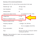
The FirstWatt F4 Owners Manual can be downloaded from this webpage: (link) . On page 12 you will find the table excerpted below.
Doing the math:
-0.3dB == 0.966x (proof: 10^(-0.3/20) = 0.966)
Max output before clipping = 20V peak ----> therefore max input before clipping = 20.7V peak (proof: 20/0.966 = 20.70)
Doing the math:
-0.3dB == 0.966x (proof: 10^(-0.3/20) = 0.966)
Max output before clipping = 20V peak ----> therefore max input before clipping = 20.7V peak (proof: 20/0.966 = 20.70)
Attachments
Yep, you need a preamp that can swing 20V.
I suggest a Conrad Johnson tubed preamp, they swing 20Vrms. Right now, behind me, I got such a stack.
At one point I looked at the ARC preamps but the most they swing is 10vrms. I got a hold of the factory and they told me it would not full swing the F4.
I suggest a Conrad Johnson tubed preamp, they swing 20Vrms. Right now, behind me, I got such a stack.
At one point I looked at the ARC preamps but the most they swing is 10vrms. I got a hold of the factory and they told me it would not full swing the F4.
- Home
- Amplifiers
- Pass Labs
- A guide to building the Pass F4 amplifier