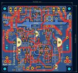
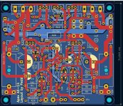
Eric, take a look at this version which has the high current traces copied to the top side also.
Apologies - missed the soldermask gerber files in the previous post - attaching a new zip file.
Good if someone else can check if this one looks fine - tks!
Attachments
Hi
This is what I see with JLCPCB


Looks ok to me but maybe someone can confirm before I order 5 PCB.
I’ve just noticed 2 little jumpers near the middle of the PCB, these were probably there on the original single sided PCB. I’ll probably replace them by 0 ohm power resistors.
Thanks
Eric
This is what I see with JLCPCB
Looks ok to me but maybe someone can confirm before I order 5 PCB.
I’ve just noticed 2 little jumpers near the middle of the PCB, these were probably there on the original single sided PCB. I’ll probably replace them by 0 ohm power resistors.
Thanks
Eric
Last edited:

I also uploaded the FH11 zip to JLCPCB and checked it out in their Gerber viewer - looks fine to me
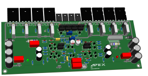
Apex AX14 - 2pairs.
Respected Sir,
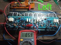
I'm having issues with dc offset.
In the Left channel I am getting dc offset 6mv, while in the right channel it is nearly 0mv. Both channel bias is set to 16mv.
Rail voltages are +/-56Volts, input+ SGND are connected to PSU GND while taking these measurements
As I went through this thread, dc offset readings seems to be fine in my case (please correct me if I'm wrong).
But I'm also looking for your expertise advice why I'm getting two different results, and how to get same readings for both the channels.
Respected Sir,
I'm having issues with dc offset.
In the Left channel I am getting dc offset 6mv, while in the right channel it is nearly 0mv. Both channel bias is set to 16mv.
Rail voltages are +/-56Volts, input+ SGND are connected to PSU GND while taking these measurements
As I went through this thread, dc offset readings seems to be fine in my case (please correct me if I'm wrong).
But I'm also looking for your expertise advice why I'm getting two different results, and how to get same readings for both the channels.
Attachments

7 mV is quite low no problem.
transistor differences can be the cause, like in the input, and need matched.
I have a servo who do also not exact 0 mv, here op amp is cause, can use a
precision one but 4mv in mine case is quite oké.
if it drifts then there is something get warm, or is you have current feedback
drift is present without measures like mine with a servo, I have open loop
hybrid by the way, tube are dc coupled to mosfets so a servo is needed and
a long delay before the relais shut speakers on.
regards
Hello everyone,
I'm looking forward to build the A40, is the PCB 1.4 by Alex is the latest one?
Or should I try something new by miles?
I'm looking forward to build the A40, is the PCB 1.4 by Alex is the latest one?
Or should I try something new by miles?
Hello Prasi Ji,Hi Indian members,
i have about 20-30 pcbs of attached apex preamp and psu which i want to get rid of.
only shipping and packing charges of inr 200. payment by g-pay. interested members can contact me via pm with qty required and postal address.
i have used it over a year and works well. no support for build will be provided. All values provided on sch and also on pcb..
regards
prasi
Do You Still Have This Board..
hi, i made this pcb. it seems to work but i have noticed that one or two of the transistors on both sides get too hot. i will recheck exactly whith one is heating and why. i think it happens when ground is connected and i have noticed some distortion in audio too.Here is the layout provided by Alex. It had a few extra holes to provide for different style components.
Hi I checked the board and found that 220 ohm resistors on both positive and negative side is heating up. I used BC 557c and BC 547c in replacement. Transistors connected to 220ohm resistors are also too hot. One more thing I noticed that there is 5v at output. I'm thinking to rebuild but it's gonna take timeHere is the layout provided by Alex. It had a few extra holes to provide for different style components.
nice build, what pcb of p30 you made?Beer accepted😀
You have a nice shop.
A40+P30 this is the final version
can it power p30 preamp ?+-24V power supply
Hi, I have built the +-24V power supply. It works very well. Enclosed the sprint file. Maybe someone finds it useful.
regards Olaf
Do the A40 needs any big modifications to run on ±70VDC with 4 pairs of output transistors,
I want to increase it's output to 250/300W @ 8 ohms
I want to increase it's output to 250/300W @ 8 ohms
Hi,
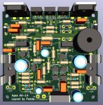
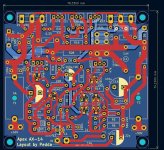
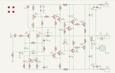
because i am interested about the Apex AX-14 amp i made a pcb with Kicad. There are little changes on the board. I want to use a Connex SMPS and i set two 470 µf capacitors and two 100nf caps. Could be changed to 22 µf, without the 100 nF.
Instead of Q1/Q2 2N5401 i changed to BC560 with different pinout. Groundlift resistor is on the pcb.
I am not sure if the zobel is right, choosing 10 Ohm/100nf. Also the boucherot filter choosed with 1 µH and 10 ohms.
But i can easyly correct that components.
Question to Apex, Mr. Mile...is it allowed to post the gerber files here?
This is the first try to design a pcb for the AX14. Perhaps i will make some changes....
If you find any mistake or i can do something better, please let me know...
Greets Peter
Attachments
voltage gain is approx 39, ratio of R11 and R8.
You can reduce gain by increasing R8, say 1k.
Hi Prasi,
Can you help me reducing the gain in the AX15 by 12db?
thanks
A40 R2.0 (WIP)
My modified version for running it off from 70VDC (theoretically)
Design is based on AlexMM's last A40 PCB

My modified version for running it off from 70VDC (theoretically)
Design is based on AlexMM's last A40 PCB
It's the AX14 with one pair. It's connected to a pair of beta15 per channel in paralell. A lot of power for the open baffle. How can i reduce the power by 10db or more?Hi Prasi,
Can you help me reducing the gain in the AX15 by 12db?
thanks
Thank you
- Home
- Amplifiers
- Solid State
- 100W Ultimate Fidelity Amplifier