Hi PeterHi,
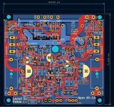
because i am interested about the Apex AX-14 amp i made a pcb with Kicad. There are little changes on the board. I want to use a Connex SMPS and i set two 470 µf capacitors and two 100nf caps. Could be changed to 22 µf, without the 100 nF.
Instead of Q1/Q2 2N5401 i changed to BC560 with different pinout. Groundlift resistor is on the pcb.
I am not sure if the zobel is right, choosing 10 Ohm/100nf. Also the boucherot filter choosed with 1 µH and 10 ohms.
But i can easyly correct that components.
Question to Apex, Mr. Mile...is it allowed to post the gerber files here?
This is the first try to design a pcb for the AX14. Perhaps i will make some changes....
If you find any mistake or i can do something better, please let me know...
Greets Peter
i think the output Thiele Network with 1µH is a bit too small. i see often with 50V rail a inductance of 4-6µH.
e.g. mooly amp,
? here it is nearly the same--> at the FH9HVX with 52V rail is 1.5µH...?
kr
chris

Hi Chris,
all can be changed. I have chose a diameter 1,32mm for the holes. Can change the coil diameter from 12 to 15 mm and chose a coil with 1,6 µh as on the FH9 XRK Mod.
One Coffee later...got 2µH,12 Wdg for 1,7µH
Thank you...
Perhaps it's better to put the Network directly to the output of the housing at the terminals/bBinding post...
Attachments
Hi all. Would this be suitable for a 600wrms power amplifier? If not, what should I change....Thanx in advance all. Have a blessed 2025PSU for FX100 include all this exept soft start. Use this soft start circuit.
I can upload my geber files for the AX14 Amp tomorrow. No guarantie, but i think it will work...
Peter
Peter
@Kleinhorn thank you! Is there a BOM for the AX14? This thread is huge, I only found one using smd Cs and Rs unlike your design. Looking for an amp build for a complete beginner, this one seems to receive great feedback.
Hi,
if i make a boom list there is always a format called "csv". I can do in an other way perhaps. I will try to copy and paste in a normal text editor...
if i make a boom list there is always a format called "csv". I can do in an other way perhaps. I will try to copy and paste in a normal text editor...
Thank you m0rten, i have madea Pdf file...
For the "testpoints" choose 6,3mm Faston connectors, print. For the input you can choose a 3,5mm connector, must not be made by wago
For the "testpoints" choose 6,3mm Faston connectors, print. For the input you can choose a 3,5mm connector, must not be made by wago
Attachments
Last edited:
I am sorry very much...
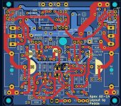
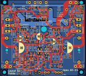
There was a mistake on my pcb for the AX14. The pinouts for 2SA1837/2SC4793 were wrong, had the wrong pinout. All others Transistors have the right pinout.
I have changed the pinout and made a new gerber file. I hope you haven't ordered as i did...
There was a mistake on my pcb for the AX14. The pinouts for 2SA1837/2SC4793 were wrong, had the wrong pinout. All others Transistors have the right pinout.
I have changed the pinout and made a new gerber file. I hope you haven't ordered as i did...
Attachments
The solution is easy.
Take little wirings to change, cross. pin 1 an 3 by cutting . I will do so too. The cap 100p put on the backside of the pcb....little wirings from pcb to the transistors 1837/4793...done
Sorry...do not want that...awful mistake happend...
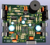
To compare a screenshot of the new pcb and an old picture
Take little wirings to change, cross. pin 1 an 3 by cutting . I will do so too. The cap 100p put on the backside of the pcb....little wirings from pcb to the transistors 1837/4793...done
Sorry...do not want that...awful mistake happend...
To compare a screenshot of the new pcb and an old picture
Attachments
Last edited:
No offense, but this file is a challenge. I just changed it a little. hope you don't mind!Thank you m0rten, i have madea Pdf file...
For the "testpoints" choose 6,3mm Faston connectors, print. For the input you can choose a 3,5mm connector, must not be made by wago
Cheers, Morten
Attachments
I had already ordered the PCBs, so will need to cut the tracks like you suggested. I may request you to post a picture once you have done the modifications.I am sorry very much...
There was a mistake on my pcb for the AX14. The pinouts for 2SA1837/2SC4793 were wrong, had the wrong pinout. All others Transistors have the right pinout.
I have changed the pinout and made a new gerber file. I hope you haven't ordered as i did...
Thanks
- Home
- Amplifiers
- Solid State
- 100W Ultimate Fidelity Amplifier