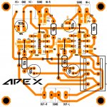
The vinyl. Peel it off the backing and stick to your paper then print onto the vinyl. Position the board over the image, tape it in place so it won't shift. Flip it over and iron the back side of the paper for 1-2 minutes with the iron on the highest setting. Quickly douse it in cold water to set the toner. Peel it away and check for voids. You can touch up any voids with black permanent marker. You can use exactly the same process for attaching the Silk if you choose.
Blessings, Terry
thank you, Terry. sorry for hounding you, but i realize i dont have iron transfer for the non-inverting LinearPre. would you also be willing to share that as well?
thank you.
thank you, Terry. sorry for hounding you, but i realize i dont have iron transfer for the non-inverting LinearPre. would you also be willing to share that as well?
thank you.
The Non-inverting LinearPre uses a few SMD parts on the foil side. Not for everyone but that is how I did it. If still interested I am attaching those files.
Attachments
The Non-inverting LinearPre uses a few SMD parts on the foil side. Not for everyone but that is how I did it. If still interested I am attaching those files.
not a problem. thank you, Terry. well done!
Is the F100 Power supply suitable to my Apex A23? Just wondering about that low filter capacitance for both channels.
Sir,
If we can just connect transformer with rectified and filtered voltage then amp definitely works fine. I think the PSU is just helping in worst case while the circuit becomes short circuit Thanks.
If we can just connect transformer with rectified and filtered voltage then amp definitely works fine. I think the PSU is just helping in worst case while the circuit becomes short circuit Thanks.
Is the F100 Power supply suitable to my Apex A23? Just wondering about that low filter capacitance for both channels.
I used 10,000uF caps in mine. I think that is sufficient. This is not class A. I like having the psu and protection in the same board.
I like having the psu and protection in the same board
Totally agree. That's why im interested in the F100 PSU.
In Comparison to some other "audiophiles" using 50.000µF per Channel and more, I'm just asking myself how much capacitance would be really worth the effort. I know there are many many discussions in many many forums about this. I'm thinking of that F100 PSU in a mono version with a few more footprints for caps to find out. Maybe I should make another PCB 🙂.
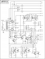
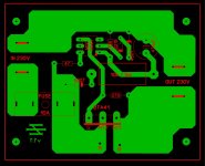
PSU for FX100...
Attachments


PSU for FX100...
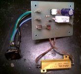
Mr. Miles... Do you have Iron transfer layout and component overlay files ?
PSU for FX100...
Hi Mile,
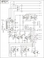
Comparing the F100 PSU to the FX100 PSU and I only see a small difference in the protection circuit. Is the protection circuit better in the FX supply?
Attachments
Hi Mile,
Comparing the F100 PSU to the FX100 PSU and I only see a small difference in the protection circuit. Is the protection circuit better in the FX supply?
Yes, negative DC detect is better.
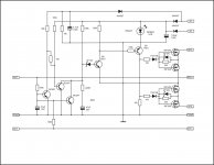
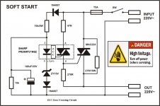
Someone who can make a pcb for this protection circuit?Like this
Attachments
I'm currently planning of making a PCB, including: psu, protection, clipping indicator and softstart. So which protective circuit shall it be?
I'm currently planning of making a PCB, including: psu, protection, clipping indicator and softstart. So which protective circuit shall it be?
PSU for FX100 include all this exept soft start. Use this soft start circuit.
Attachments
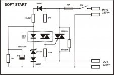
Another direct to mains circuit.
Look at that metal encased resistor just asking to electrocute a wayward finger !
Look at that metal encased resistor just asking to electrocute a wayward finger !
AC Mains wiring and conducting parts of course should be isolated or covered. If appropriate precautions are made, i don't see any problem, making mains conducting PCBs.
Another direct to mains circuit.
Look at that metal encased resistor just asking to electrocute a wayward finger !
Thanks AndrewT,
Yes, you must pay attention to this circuit because the entire PCB is operated by the mains voltage 110/220VA!!!

If you pretend to use also Zero crossing turn-on soft start, look at the variation of the Apex soft start circuit (see attach.)
The IC is available and also cheep and because now using ZCC
the time constant RC can be shorter and R_soft start resistor smaller in value and power rating
LP
Dragan
Attachments
MOC3041 is zero crossing optotriacThanks AndrewT,
Yes, you must pay attention to this circuit because the entire PCB is operated by the mains voltage 110/220VA!!!
If you pretend to use also Zero crossing turn-on soft start, look at the variation of the Apex soft start circuit (see attach.)
The IC is available and also cheep and because now using ZCC
the time constant RC can be shorter and R_soft start resistor smaller in value and power rating
LP
Dragan
Terry,
what are the small oval yellow caps you use in the fx100?...ceramic?
thanks,
freeman
- Home
- Amplifiers
- Solid State
- 100W Ultimate Fidelity Amplifier