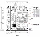
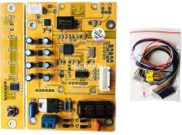
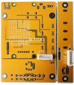
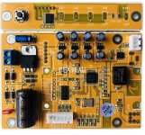
sorry : : Output resistor then inverting input for buffer or more gain. Both op amps are inverted pin input as said. Pretty easy. It is not swapping original miro's, but more for passionates who already begunn with single op amps from miro1360's pcbs.
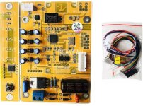
As I have not tried AKM digital recievers, I ordered this one to test with one of the DAC's I'm building. It has an I2S input, so I could use this and an Amanero and have USB, Coax, and toslink inputs to the DAC I end up using it in.
It's worth a try 🙂
It's worth a try 🙂
Attachments
Anyone that has tried this version of AK4118 DIR?As I have not tried AKM digital recievers, I ordered this one to test with one of the DAC's I'm building. It has an I2S input, so I could use this and an Amanero and have USB, Coax, and toslink inputs to the DAC I end up using it in.
It's worth a try 🙂
Attachments
Some updates more related to York but I think it's worth to post it here 🙂
When I used some other USB audio interfaces there was an issue in MacOS that I could not control the volume by the standard OS means, it was basically disabled. And the reason is that these interfaces did not implement volume control, so they were always outputting 0dB digital signal. Except for Windows, where volume control was still possible but handled by Windows mixer. But some Interfaces did implement it in MacOS too.
So I've been thinking that, well, it is possible to implement volume control and handle it on the device side. And it does not have to be digital 🙂
About a year ago I designed a relay volume attenuator module.
Today finally implemented the volume control feature and put everything together:

The attenuator is connected by I2C bus and supplies from USB side. The signal ground of the attenuator is isolated from control side.
And it works 🙂 I recorded a short video as a demo, in the video I scroll the Windows volume control slider:
When I used some other USB audio interfaces there was an issue in MacOS that I could not control the volume by the standard OS means, it was basically disabled. And the reason is that these interfaces did not implement volume control, so they were always outputting 0dB digital signal. Except for Windows, where volume control was still possible but handled by Windows mixer. But some Interfaces did implement it in MacOS too.
So I've been thinking that, well, it is possible to implement volume control and handle it on the device side. And it does not have to be digital 🙂
About a year ago I designed a relay volume attenuator module.
Today finally implemented the volume control feature and put everything together:
The attenuator is connected by I2C bus and supplies from USB side. The signal ground of the attenuator is isolated from control side.
And it works 🙂 I recorded a short video as a demo, in the video I scroll the Windows volume control slider:
6E5P
Different spice models (PSpice anD LT spice) for measured tube in triode mode.
Also with static settings for typical 350V Vb.
All in ZIP folder
.
This is limiting factor because tube can be used with higher PS voltages, acording to high G2 250V.
BUT for that high Vb is a must more than 450V... All that implicate higher rectifier Vanode and decrease choice of Rectification tube, and make PS capacitors high voltage values min 500 to 550V. Also limiting the choices of C in PS.
.
So power supply value is determining factor with 6E5P tube.
Of course that it cam be used (wrongly typical) lov voltage higher current or low current, but the tube is linear in HV region too and that is the one for better sound. 200V of Va ot around - not 120V...
.
So some design considerations are:
R load is chosen to keep THD low but in the same time to lower Vb as it can be...
Biasing is not critical I chosse 2.4V to be optionally battery biased...
.
I will check for values of elements in Spice and make some dynamic results.
Attachments
The big issue is that most of the DIY-ers simple dont understand enough things about markings and values concrning Power supply... 🙁
Va = anode voltage, voltage between Cathode and Anode
Vb = battery voltage, power supply voltage to the circuit
Vb = abs(-Ug) + Va + Vdc@Rload, (for automatic grid bias with R in cathode)
Vb = Va + Vdc@Rload, (for fixed grid bias with external -Ug to grid)
-Ug = negative grid bias
Vdc@Rload = drop of DC voltage on load resistor
.
So many "generic" PSs are in use, most of them are in 250V to 350V range.
But most of the tubes needs simply more Vb to be set in proper way...
.
And then we are 90% in position to adopt and compromise active audio circuit to the given PS,
then opposite, logic way is to design PS compatible to the circuit optimum settings.
.
For the 6E5P and 500V DC capacitors limit, somewhat like this PS is welcome, of about Vb=435V, and 470Vmax to be under 500V of capacitor limiting vaue. Max C on 5U4GB is 47uF (50uF will be OK), calculate (depends on transformer Rdc windings) and add 2 x R to rectifier anodes of about 120 - 150 ohms. o have in mind available F&T dual 50uF+50uF / 500V standard caps... Chokes are prety much available and say standard for 100mA current. And Transformer is 2 x 400V AC C.T. minimum 70mA wire, (because in transformer current are each period SQRT(2)/2 then total Io, peaks device will suck from the capacitors... That is transformer of 800V x 0.07A = 56W total minimum and without the losses, so it is about 65W minimum, better 80-100W...
.
Last edited:
Hi Zoki is 435V too much?
Va = anode voltage, voltage between Cathode and Anode
Vb = battery voltage, power supply voltage to the circuit
Vb = abs(-Ug) + Va + Vdc@Rload, (for automatic grid bias with R in cathode)
Vb = Va + Vdc@Rload, (for fixed grid bias with external -Ug to grid)
-Ug = negative grid bias
Vdc@Rload = drop of DC voltage on load resistor
Updated BOM for populating Miro AD1862_dac_v1-3 pcb from Mouser.
https://www.mouser.ca/api/CrossDoma...ync=False&setPrefSub=False&clearPrefSub=False
AD1862 DAC chip from Digikey, Rochester, or elsewhere.
BTW does anyone have an extra pair AD1862 available?
https://www.mouser.ca/api/CrossDoma...ync=False&setPrefSub=False&clearPrefSub=False
AD1862 DAC chip from Digikey, Rochester, or elsewhere.
BTW does anyone have an extra pair AD1862 available?
@mabma
Hello,
I see you have chosen X7R and not in stock. Please swap them by NPO and if ThT swap by smd the size to solder them across the two holes. Stray inductance are very not liked for those shift registers.
Add two 1655 as benchmark, not idéal on a socket but you get an idea of one of best new tech easy opa.
I/V : try carbon and also wirewound Vishay AE...something: the green body one, idéal mariage with the 1655.
For the two 4,7 and 47 uF of the ad1862 (or 2,2 uf and 24 uF circa) Nichicon L extra low leakage is fine as well.
You can also try something wima FKP2 1,5 nF across the I/V resistor, so easy to swap and let your ears choosing....usefull for fast VFA op amps.
Last edited:
Here are some sircuits for 6E5 tube in triode mode. Settings optimizad for Vb of about 350V.
Very low distortion, sufficent gain, low output impedance less than 1K about 900 ohms, no buffer need for higher next Rin, very good BW, verry low phase shift.
BUT with this component values. Don't decrease Co, don't change Ck, don't change RL value...
Biasing is chosen for -2.4V cca. to be possible to make it with 2 x 1.2V serial connected batteries in cathode.
Value of power for R load is critical and has to be as stated for this element to be just warm. Otherwise it would be huge thermal dissipation causing overhating R and overhating all other elements...
.
Anode voltage Va=166V cca,
Cathode current Io=30mA cca.
Grid bias -Ug=2.4V cca.
Anode dissipation Pa=5W (less than 50%)
...
Other similar tube pentode, also in triode mode connected can be used. Maybe a slight better?
6E6P
.

...
6E6P
.
...
Yes - 6E5P wasn't my taste in tonality at all. ECC40 is king in my system, on the basis of tonality. Everything for me is tonality - acoustic instruments, voices, Steinway pianos. All instruments I know well. And all the valves I use, as with the capacitors, have been carefully auditioned in my system with the same test tracks I've used for at least 5 years.@Zoran I wonder how 6E5P is going to sound in this application. I tried it as a driver for 6S33S and I did not like the sound at all - 6S33S sounds amazing with other tubes.
If you design on the basis of theory you would use a valve with a lower Rp, like 3K, and put 6mA or more through it. But that won't necessarily give you the right tonality. Only listening to the valve stage in your system and with your familiar test tracks will tell you what it actually sounds like. At least that's the way I've always done it and believed in. Horses for courses.
I liked 6AC7 as a driver. It was a bit surprising. I got lucky and found a box of them from late 1940s cheap on ebay.
However, I discarded the idea of 6S33S due to enormous amount of iron they require to sing well. They also need at least 30-60 min to warm up to the sound. Their working point is super critical to the tonality. I am happy to share details if you are interested.
However, I discarded the idea of 6S33S due to enormous amount of iron they require to sing well. They also need at least 30-60 min to warm up to the sound. Their working point is super critical to the tonality. I am happy to share details if you are interested.
Hi, I have finished Nelson Pass’s DIY Front End 2022. Now the setup is: 39R I/V resistor on Sowter 1495 primary side.
At the secondary side only the FR2022 without C1 and C2 input caps.
According to the first impression this configuration sounds better than the previous tube SRPP stage.
Tomorrow I’ll take some measurement.
At the secondary side only the FR2022 without C1 and C2 input caps.
According to the first impression this configuration sounds better than the previous tube SRPP stage.
Tomorrow I’ll take some measurement.
- Home
- Source & Line
- Digital Line Level
- DAC AD1862: Almost THT, I2S input, NOS, R-2R

