I didn't say that it was a "rule", though I do see it as a goal. What I did say is that with certain tubes Rl is critical, and I gave the example of the type 26. I did extensive listening tests on it from 27K up to 47K and the sound got cleaner the closer you approached 47K. There's no doubt in my mind that this is the case - I spent a day trying out different operating points and listening carefully. So where it's possible I try tubes out at 5x Ri. Sometimes this is limited by the B+, so I come down to 4x or 3x Ri if I have to. But not lower. I try different Rl resistors with different tubes on a case-by-case basis. It's the same with OPTs. I generally prefer a 300b with a 4K or 5K OPT for instance, though some use as low as 2.5K. The sound is cleaner. Once again, all is tonality in my musical world.It is not true that rule 1 : 5 = Ri : RL exists. Rather some mathematical deprivation for maximum efficiency in literature is 1 : 2 = Ri : Rl
Seavan - do please try out a 5x load resistor for a triode, and give us your listening results! And compare it with 4x and 3x.
Last edited:
HiI did extensive listening tests on it from 27K up to 47K and the sound got cleaner the closer you approached 47K.
Did Yoy made the tests with same pover suply in same set up? Just changing Value of R load?
Hello Zoran - yes, exactly the same power supply and setup for the type 26. I just swapped in different anode resistors and listened to my standard test tracks. This was in filament bias so the cathode voltage would probably have stayed the same if I remember correctly. It was a year or two ago. I spent a whole day listening and changing resistors. The difference was quite audible. This was in the driver stage for my 2-stage SE amp, so it's a very revealing setup. I try out different value anode resistors for other valves also. I listen to everything.
Correct me if I am wrong here. I think increasing Rload without touching anything else will reduce Vplate. I wonder what really made an impact - Rload or Vplate. You can reduce Vplate by decreasing V+ without increasing Rload - would it make the same impact? Based on my experience, Vplate may change the sound for some tubes. I will experiment with ECC40.Hello Zoran - yes, exactly the same power supply and setup for the type 26. I just swapped in different anode resistors and listened to my standard test tracks. This was in filament bias so the cathode voltage would probably have stayed the same if I remember correctly. It was a year or two ago. I spent a whole day listening and changing resistors. The difference was quite audible. This was in the driver stage for my 2-stage SE amp, so it's a very revealing setup. I try out different value anode resistors for other valves also. I listen to everything.
Hi Andy,Hello Zoran - yes, exactly the same power supply and setup for the type 26. I just swapped in different anode resistors and listened to my standard test tracks. This was in filament bias so the cathode voltage would probably have stayed the same if I remember correctly. It was a year or two ago. I spent a whole day listening and changing resistors. The difference was quite audible. This was in the driver stage for my 2-stage SE amp, so it's a very revealing setup. I try out different value anode resistors for other valves also. I listen to everything.
with changing only R Load in the tube sircuit, and with all other elements are remain the same, Yoy changed completely tube circuit...
Even the Power Suply, Vb is not constant any more IF it is not regulated type.
.
What happened:
a) The R load value is doubled
b) Vdc drop on R load is increased
c) Tube has significantly less Anode voltage Va
d) Rk is the same, but vith lower Va Current trough the tube is less.
e) Anyway with this lower current voltage drop in doubled R Load is huge
f) with increased value of R load Zout is higher
Result.
All main tube parameters in circuit are significantly changed, It is not the only R load value...
That is different circuit
.
That is not valid test for R Load value change. Valid test will be to increase PS value to maintain the loss od Volts,
for keeping the same working point condition. Va, Ia
.
I will post the graph for illustrate this
Cheers
.

Yes - it's a question of attribution. Yes, there are various factors at work here, we know that. So what makes the significant changes in sound? First, the changes in B+ are quite small. So on the one hand we have the load resistor, on the other hand we have a change in the current going through the tube. If I am going to make an attribution based on collective experience of varying the load, not only with several tubes but also with plate chokes and the primaries of OPTs, I am still going to say that it's the load that makes the most difference. Higher loads sound cleaner. Here are some old notes with the 26 tube.
Attachments
Last edited:
This a hypothetical settings for 22K Rload
Power supply Vb is just about 260V, and in this case is constant.
(It ia for simplifying things, and if is not regulated, the load line will be same but in slight different position with current in case of unregulated power supply...)
Va=110V Ia=7mA

R load change to 47K
Working point is somwhere on this line.
For more accurate graph Spice modeling should be consulted, With values of power Supply elements and cathode resistor value.
But change in working environment is dramatic...
So it is not R load vaue change only.

Power supply Vb is just about 260V, and in this case is constant.
(It ia for simplifying things, and if is not regulated, the load line will be same but in slight different position with current in case of unregulated power supply...)
Va=110V Ia=7mA
R load change to 47K
Working point is somwhere on this line.
For more accurate graph Spice modeling should be consulted, With values of power Supply elements and cathode resistor value.
But change in working environment is dramatic...
So it is not R load vaue change only.
Hello Zoran. Could you repeat this with a B+ of 360V-370V as in my examples? A B+ of 260V makes no sense at all with a 47K anode resistor. The current is too low and you only have 85V on the anode. I would never use such a low B+. But I would be very interested to see your simulations for a B+ of 360-370V. That would be educational.
Yes I can repeat with Your values but in Spice. You used special case possible only with DHT with constant biasing method of about mid point with 9.5V to 11V. Because R from Cathode and heaters power suply is constant 10 ohms. Because of the fluctuation of Vb DC value PS it would be useful to have Power supply configurations and values of elements? I persume thet PS was passive made from some RC or LC networks?Hello Zoran. Could you repeat this with a B+ of 360V-370V as in my examples? A B+ of 260V makes no sense at all with a 47K anode resistor. The current is too low and you only have 85V on the anode. I would never use such a low B+. But I would be very interested to see your simulations for a B+ of 360-370V. That would be educational.
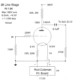
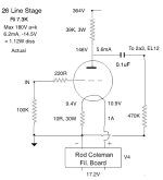
I know the 26 well, since I've built with it many times over the last 20 years. The 10 ohm cathode resistor in filament bias is a standard value and it enables you to use some good sounding NOS resistors. So that fixes the cathode voltage at around 9.5 to 10V. Over the years I took a lot of notes on the 26, and a few users noted that 5.6mA was a sweet spot. In the end I used that with a 39K anode resistor because I had some good sounding NOS resistors. You will find that you can't go below 31K anode resistor with a B+ of 360V, given that the maximum for the 26 is 180V a-k at 6.2mA and -14.1V. So when I listened to several different operating points with resistors like 27K and 31K, I used a lower B+. I needed to push up the B+ to 360V to get the best sound. So if you want to model my operating point I'd use this schematic. You will also note that this operating point is the middle one of three listed in the 26 data sheet. Coming back to the multi-bit DACs it's possible to use a 26 stage with a higher value I/V resistor for the AD1865, given that values of 200R or even 300R (reportedly used by AN) have been used. So not irrelevant.


Last edited:
Actually when we use for instance 39K R Load, and total value of termination resistance is for instance 470K
(as next resistor input on the tube amplifier), we have AC componenet and load line as parallel value of theese resistance...
So, the real load line is 36K.
With smaller R input on "next" device, as solid state, dor instance 47K, our AC load is gravitating to 21.3K.
That is the rason why the R Load value has to be higher than one with static load line settings, has to be additionally calculated with respect to AC load. And that is termination resistance in parallell to R input resistance, all that in parallel to tube Anode R load...
(Source is literature, and can be verified with spice too...)
.
I made some spice models for 26, can be useful? One is with RCA datas, other is with Thomas Mayer measurements datas. Mister Thomas didnt wrote necesary data about measurements, like -Ug step, mA scale step and Anode voltage step... 🙁
I spend an extra time to try to make this graph usable...
.
ZIP folder contains for each data standard and DHT model. 4 models are inclouded with graphs.
.
I will check now in spice what is happenning with circuit.
cheers
.
Attachments
HelloThanks miro1360, gave the code a try myself, used ssd1306 I2C and here is the result.
View attachment 1216434
I realized some errors in the code in the sense that LRCLK carries stereo signal instead of single channel, therefore it had to be adjusted.
HD44780 20x4 LCD will be the same, slight changes from the last code instead of Hz the code is now calculated in KHz and displayed as such, since I am out of time this weekend so I leave further tweaking to the DIY community. I guess as POC it works.
Here is the modified code for SSD1306 I2C oled.
Can you share wiring diagram with Arduino Nano ?
Hello
Can you share wiring diagram with Arduino Nano ?
Wiring is very simple and is defined in the code as well:
Display is I2C compatible so it is connected with Arduino I2C pins (I think I used the hardware I2C)
Next pin the LRCLK ot is defined in the code as:
const int lrclkPin = 2; // Replace with the appropriate pin number
The next pin is Gnd.
Andy
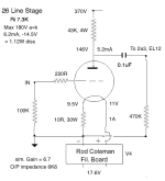
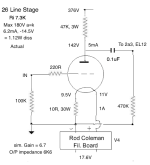
I went trough the spice for Your sch. There was some limitations about fixed Vb...
But other things was OK.
The Ug value is pretty fixed and stady with changing R load value. It ia sa sort of some CCS in Cathode.
So it is aways in center of heter Vdc value. Current for 11V at one side is smaller than should be because of fixed Rdc of the heaters. And it is 0.96A against 1.05A that should be... That is 100mA diff.
10 ohm R could be trimmed a bit with parallel 110 ohm resistor or stronger pot to match first heating current, and second that will change -Ug a bit lower with resultong a bit more current, and bit less Va...
.
The values are pretty matched, ecept for Vanode which is 10V higher on the sims.
Interesting thing there is no correspondent increase in Output when changing Load.
Probably because of that sort of CCS in Cathode. No change of THD with higher R load. I mean it is, but on 4th decimal point...
.
Consider to add 2.2uF at the 0.1uF C @ output - take look at the output impedance graph. With 0.1uF impedance starting to increase rapidly just below 1KHz... Also on the FFT is significant PSRR diff. with masking. That will be much smaller in praxis but it exist, and can give more resolution and deep silence...
.
.
Last edited:
Coming back to ECC40 as a tube output stage, I came across this distortion chart which makes interesting reading. Gunf's choice of ECC88 looks good too. I'd say that 22K load is good for ECC88 but it seems low for ECC40 despite the good data. I would imagine ECC40 would be better with a higher value anode load, and I use 39K. Zoran would like it at 22K no doubt! Anyway, it confirms that ECC40 isn't a random choice of valve but actually a very good one.

Last edited:
Hi, are these the most recent gerbers for these variants?
AD1862
AD1885
PCM63
Thank you for pointing this out, I repaired the GND pin and here is new gerber for the PCM63P 😊 😉
AD1862
Use this link for more details:
https://electrodac.blogspot.com/p/dac-ad1862-almost-tht-i2s-input-nos-r.html
Note: 8th pin on the I2S input header is missing connection with the GND (on some of my PCBs this pin is unconnected, if you are going to use it, solder it with the nearest GND pin on the header)
People who are selling brand new unused AD1862 or AD1865 chips:
I want to thank...
AD1885
AD1865 ... the same principle
Not having AD1865 DAC in the collection?
Here is one ... the same PCB changed for AD1865 DAC.
It is tested by @Vunce.
Power supplies are slightly different!
analog part: +5VA, -5VA
digital part: +5VD
Have DIY fun 🙂
Not having AD1865 DAC in the collection?
Here is one ... the same PCB changed for AD1865 DAC.
It is tested by @Vunce.
Power supplies are slightly different!
analog part: +5VA, -5VA
digital part: +5VD
Have DIY fun 🙂
PCM63
There is one small thing. On the I2S connector on the PCM63 board (pins 2,4,6 and 8) pin 8 says GND, but it is not connected to GND. I connected that from the bottom (pins 7 and 8) so as not to change the connector I used for the AD1865. I have no idea why it is not connected to GND and it says GND? I didn't notice before. This is important to me because the AK4113 and the JLS output part are grounded through that pin to DAC GND.
Thank you for pointing this out, I repaired the GND pin and here is new gerber for the PCM63P 😊 😉
Hi Andy,
did You measure distortion with external sound card or computer line input?
Because if You measured with sound card or computer input, they typically have
low input Rin to ground. About 10K as OP amp devices...
Now, as ECC40 and other tubes has higher Ri leading to higher Zout, that 10K is very hard load almost the same calue as Zout.
That is giving higher THD figure, loss in amplification caused by low load, decreased PSRR... 🙁
.
You can measure value of Rinput to the sound card becaise it is in most cases first element at the input jack.
With MacBookPro it is about 10K and with most of the sound cards too.
.
Solution for lower sygnals high impedance input can be JFET buffer, battery opperated. With 1Meg or higher on imput, for acting as high impedance load and not to overload the DUT?
.
But again higher R Load value need Higher Vb value, and You restricted to +320V cca,
.
I can make a more complete spice test.
.
did You measure distortion with external sound card or computer line input?
Because if You measured with sound card or computer input, they typically have
low input Rin to ground. About 10K as OP amp devices...
Now, as ECC40 and other tubes has higher Ri leading to higher Zout, that 10K is very hard load almost the same calue as Zout.
That is giving higher THD figure, loss in amplification caused by low load, decreased PSRR... 🙁
.
You can measure value of Rinput to the sound card becaise it is in most cases first element at the input jack.
With MacBookPro it is about 10K and with most of the sound cards too.
.
Solution for lower sygnals high impedance input can be JFET buffer, battery opperated. With 1Meg or higher on imput, for acting as high impedance load and not to overload the DUT?
.
Should be checked. 🙂I would imagine ECC40 would be better with a higher value anode load, and I use 39K. Zoran would like it at 22K no doubt! Anyway, it confirms that ECC40 isn't a random choice of valve but actually a very good one.
But again higher R Load value need Higher Vb value, and You restricted to +320V cca,
.
I can make a more complete spice test.
.
- Home
- Source & Line
- Digital Line Level
- DAC AD1862: Almost THT, I2S input, NOS, R-2R