@Seavan curious how you mounted it 😆
$51 for a cap is an absolute no-go for me, sorry, will try something exotic when I'll have some time to look for URSS things...
I don't expect big wonders from this B+ regulator, yet for sake of curiosity, after trying and analogue PS for the AD811, i'll try it to see whether the tube thermal noise can be beaten.
I guess i is similar to your Salas HV however, concept is the same, being a shunt. Of course, implementation can differ. Here there's an interesting feedback.
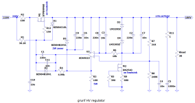
So fellows, as a new year's greeting, a board for @grunf 's HV regulator, as presented in one of his answers in the thread.
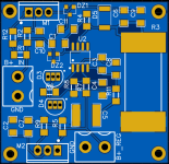
All SMD, measuring just 41x43mm (heatsinks excluded), is a nice add on between the PSU and the CCS, yes, goes between my two previous boards, in the b+ section of course.
Plug 1 side of the B+ of my psu board to the input terminal, with 220VDC in you should get 180VDC ripple free at the output.
I would then connect the output to the 2 b+ tube board inlets, I know that grunf comes to correct me saying "use two reg boards, one for each triode of the 6n23p", but i guess that currentwise it should work 😀
You are of course free to test with 2 boards, one for each side.
This boards stems from my curiosity to test a b+ regulated supply in tubes, since I've never done this before, and since if get a wonder like in the AD811 board, well, i will revise all my ideas about super ultra mega iper refined supplies (ok, this is perhaps not super ultra mega iper, but a big step beyond my basic 5$ board).
Questions, doubts, opinions, corrections (especially from the author) are more than welcome!
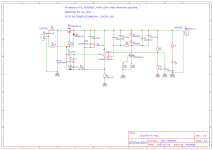
Attached are original schematic, my schematic, BOM and Gerber.
Happy new year guys ! 😛
All SMD, measuring just 41x43mm (heatsinks excluded), is a nice add on between the PSU and the CCS, yes, goes between my two previous boards, in the b+ section of course.
- IT IS NOT TESTED YET
- in the BOM I compiled additional quantities of components for my purposes, so if you want to build only one or two, please amend the quantities.
- do no forget heatsinks!
- start soldering ADA4610 first, then the SMD zeners DZ1 and DZ2, resistors, capacitors, the few THT components, MOSFETs, the big SMD 5W resistor, terminal blocks.
- for 2W zener D5, look for SMZ24 2W.
- regulator LM329DZ is EoL, though quite easy to be found around (not China). There are some equivalent, but for DC stability and noise figure we prefer this one.
Plug 1 side of the B+ of my psu board to the input terminal, with 220VDC in you should get 180VDC ripple free at the output.
I would then connect the output to the 2 b+ tube board inlets, I know that grunf comes to correct me saying "use two reg boards, one for each triode of the 6n23p", but i guess that currentwise it should work 😀
You are of course free to test with 2 boards, one for each side.
This boards stems from my curiosity to test a b+ regulated supply in tubes, since I've never done this before, and since if get a wonder like in the AD811 board, well, i will revise all my ideas about super ultra mega iper refined supplies (ok, this is perhaps not super ultra mega iper, but a big step beyond my basic 5$ board).
Questions, doubts, opinions, corrections (especially from the author) are more than welcome!
Attached are original schematic, my schematic, BOM and Gerber.
Happy new year guys ! 😛
Attachments


I sense tube IVs are in vogue, but wanted to share my latest Miro DAC setup - sans tubes. This one combines PCM63 with the vintage D1 I/V stage. This is a very nice combo and it seems the D1 adds some sweetness to soften the PCM63P. It might be ever so slightly less resolving than the Burson V7s, using the onboard opamp IV of Miro's board, but the toe-tapping factor of the D1 is up compared to these. Punchy and with a huge sound stage. Of course, this is in the context of my system and ears...and I can imagine some would find D1 too mellow in a different context, or be put off by specs that are surpassed by newer versions/options. I think this one may graduate from plank to chassis 😊
Credit goes to @Zen Mod for his help in getting the D1 and its 30v shunt singing.
Cheers

Credit goes to @Zen Mod for his help in getting the D1 and its 30v shunt singing.
Cheers
Hi,
Well done.
If one want to remove too much percieved sweetness, according tastes, whole setup; I'd remove all the CMF55 for Yageo 0207CF 1 or 0.1%. Or even carbon at some areas.
You also can dlip the D1 board 90° to make the wires from the DAC board to D1 much shorter.
Of course you can play with the 4 caps.
What is the Gemini reg from "Ze Migthy", please ?
Hi, does anyone have the simulation file for Grunf's Tube I/V? And a model for 6N1P?
I'm hoping to have some time with the computer today.
TIA
I'm hoping to have some time with the computer today.
TIA
Well done. I would probably go with TH components for the first time, it's easier to start with. R3 gets quite hot and instead of it you can put another CCS so that the mosfet can be on the heatsink which reduces the thermal load of the entire PCB. Increase the PCB a little, increase the spacing especially around M1 and everywhere where HV is present. I would maybe remove the ground plane or increase the spacing between traces and pads.So fellows, as a new year's greeting, a board for @grunf 's HV regulator, as presented in one of his answers in the thread.
All SMD, measuring just 41x43mm (heatsinks excluded), is a nice add on between the PSU and the CCS, yes, goes between my two previous boards, in the b+ section of course.
- IT IS NOT TESTED YET
- in the BOM I compiled additional quantities of components for my purposes, so if you want to build only one or two, please amend the quantities.
- do no forget heatsinks!
- start soldering ADA4610 first, then the SMD zeners DZ1 and DZ2, resistors, capacitors, the few THT components, MOSFETs, the big SMD 5W resistor, terminal blocks.
- for 2W zener D5, look for SMZ24 2W.
- regulator LM329DZ is EoL, though quite easy to be found around (not China). There are some equivalent, but for DC stability and noise figure we prefer this one.
Plug 1 side of the B+ of my psu board to the input terminal, with 220VDC in you should get 180VDC ripple free at the output.
I would then connect the output to the 2 b+ tube board inlets, I know that grunf comes to correct me saying "use two reg boards, one for each triode of the 6n23p", but i guess that currentwise it should work 😀
You are of course free to test with 2 boards, one for each side.
This boards stems from my curiosity to test a b+ regulated supply in tubes, since I've never done this before, and since if get a wonder like in the AD811 board, well, i will revise all my ideas about super ultra mega iper refined supplies (ok, this is perhaps not super ultra mega iper, but a big step beyond my basic 5$ board).
Questions, doubts, opinions, corrections (especially from the author) are more than welcome!
Attached are original schematic, my schematic, BOM and Gerber.
Happy new year guys ! 😛
The same regulator can be more complicated, I added another CCS and a low-noise reference instead of 2x LM329, so I should reconsider that version when this one is mastered.
Attachments
Hi Guillaume,Hello Tan,
How does it compare to jlsounds interface ?
Thanks
I did a comparison session with a friend of mine over the last weekend.
The test was done on PCM63 DAC with stackable USB-I2S, since the JLSounds and York can both be easily swapped by means of unplugging and plugging in.
Both of us thought that the difference is rather discernible, could easily be picked out.
Both JLSounds and York are powered by a regulated supply on the USB and the clock/reclock side is powered by +5VD from the DAC on the board.
The JLS sounded more open, with more space between the instruments. I feel that the JLS plays with more resolution such that there are more intricate details especially on strings.
The York has more body and flesh, more forward sounding. A slight Less resolution than the JLS, a slight touch less on the finer details. However, the warmth of the York has some magic on vocals which i love. One thing i also noticed that with the York, the background seems darker and quieter.
I have always has a little thing that I struggle with the PCM63. In my system, the PCM63 is a tad brighter than all the other DAC in the Miro's stable of R2R DAC designs. The York seems to be something that complements the PCM63. Somehow i suspect that it may not match as well for the AD1865 and TDA1540, which tend to sound on the warmer side of things.
I soldered u.fl connectors on the York so that i can easily test it without the reclocker board so that i can compare it against the Amanero (legit board). This was done on the PCM1704 board. The York is easily better than the Amanero (modified to accept external 5V) in most aspects. The Amanero sounded clinical and dry as compared to York.
Now i wonder how York can fare with better XO.
NDK NZ2520SDA crystals from Digikey is only a few dollars, but It is not easy to change the XO due to the surrounding tiny smd parts surrounding the two XO.
JLS configuration is done using hardware - resistors/jumpers.
York configuration is done using software tool, and offers wider flexibility than JLS.
JLS generates more heat from the transistor regulation (5V down to 3.3V) on the small board, while York has much less heat.
I would say York is a good board , adding another option for peeps here. Cost slightly more than Ali Amanero clones , and of course a little much more if you choose to add a reclocker. It is still very slightly cheaper than the JLS board. Cost difference aside, I think it is worth exploring it with different DACs. For me, it would easily replace the Amanero. Between JLS and York, it becomes a matter of personal taste. In short, I am not disappointed with York at all and I am pleasantly surprised by it.
Wishlist for York:
1. A good comprehensive user guide
2. Footprint for different XO for users to experiment.
@eclipsevl
Note : This is not a solicited review, i paid full price for my boards.
A little DHT tip for @andyjevans . In new DHT year... 🙂
Classic KC3 triode, beautiful boxed huge anode (for given A dissipation)
Higher mu, lower Ri (somehow about ECC82 section)
.
Not cheep, bud not so expensive and still available. Long life too... 🙂
Very small distortion.
With input of 220mVp-p (110 ohm Riv for 2mAp-p all range AD and BB DACs)
Output is 1.9Vrms, 5.37Vp-p - more than enough, THD from 0.03% to 0.08%
Ho huge Vb neded about +320V to +350V will do the job, Zout is 6.2K
good for tube preamplifier OR tube amplifer input...
For other inputs buffer is solution...
.
Off-course, i made two spice models, one for DHT one for classic
.
Cheers
A guy from Germany ofering two pairs on ebay - google.
.
Code:
****  KC3 Composite DHT *****************************************
* Created on 12/28/2024 10:15 using paint_kit.jar 3.1
* www.dmitrynizh.com/tubeparams_image.htm
* Plate Curves image file:
* Data source link:
* Model made by Zoran DIY audio member
*
* Vh    Ih
* 2V    0.065A
*
* Ia_max    -Ug_max    Va_max     Pa_max
* 7mA        -0.4V    150V    1W
*
* Capacitances Cgk, Cak estimated.
* Capacitance Cga from datas
* Cgk    Cak    Cga [pF]
* 5    4    6.5
*
* Class    Va    Vg1    Ia    Ra    mu    Ri
* A    135    -1.5V    1.2mA    2380    25    40K
*----------------------------------------------------------------------------------
.SUBCKT KC3_DHT 1 2 3 4 ; P G K1 K2
+ PARAMS: CCG=3P  CGP=6.3P CCP=1.9P RFIL=9.52
+ MU=30.5 KG1=1500 KP=216 KVB=480 VCT=-0.1 EX=1.666 RGI=2000
*----------------------------------------------------------------------------------
* Vp_MAX=300 Ip_MAX=8 Vg_step=1 Vg_start=1 Vg_count=13
* Rp=33000 Vg_ac=0.11 P_max=1 Vg_qui=-1.2 Vp_qui=114
* X_MIN=54 Y_MIN=35 X_SIZE=846 Y_SIZE=557 FSZ_X=1720 FSZ_Y=690 XYGrid=true
* showLoadLine=y showIp=y isDHT=y isPP=n isAsymPP=n showDissipLimit=y
* showIg1=n gridLevel2=n isInputSnapped=n
* XYProjections=y harmonicPlot=y dissipPlot=y
*----------------------------------------------------------------------------------
RFIL_LEFT    3  31 {RFIL/4}
RFIL_RIGHT   4  41 {RFIL/4}
RFIL_MIDDLE1 31 34 {RFIL/4}
RFIL_MIDDLE2 34 41 {RFIL/4}
E11 32 0  VALUE={V(1,31)/KP*LOG(1+EXP(KP*(1/MU+V(2,31)/SQRT(KVB+V(1,31)*V(1,31)))))}
E12 42 0  VALUE={V(1,41)/KP*LOG(1+EXP(KP*(1/MU+V(2,41)/SQRT(KVB+V(1,41)*V(1,41)))))}
RE11 32 0 1G
RE12 42 0 1G
G11 1 31 VALUE={(PWR(V(32),EX)+PWRS(V(32),EX))/(2*KG1)}
G12 1 41 VALUE={(PWR(V(42),EX)+PWRS(V(42),EX))/(2*KG1)}
RCP1 1 34 1G
C1 2 34 {CCG} ; CATHODE-GRID
C2 2 1 {CGP} ; GRID=PLATE
C3 1 34 {CCP} ; CATHODE-PLATE
D3 5 3 DX ; FOR GRID CURRENT
D4 6 4 DX ; FOR GRID CURRENT
RG1 2 5 {2*RGI} ; FOR GRID CURRENT
RG2 2 6 {2*RGI} ; FOR GRID CURRENT
.MODEL DX D(IS=1N RS=1 CJO=10PF TT=1N)
.ENDS KC3_DHT
*$


****  KC3 triode ******************************************
* Created on 12/28/2024 10:15 using paint_kit.jar 3.1
* www.dmitrynizh.com/tubeparams_image.htm
* Plate Curves image file:
* Data source link:
* Model made by Zoran DIY audio member
*
* Vh    Ih
* 2V    0.065A
*
* Ia_max    -Ug_max    Va_max     Pa_max
* 7mA        -0.4V    150V    1W
*
* Capacitances Cgk, Cak estimated.
* Capacitance Cga from datas
* Cgk    Cak    Cga [pF]
* 5    4    6.5
*
* Class    Va    Vg1    Ia    Ra    mu    Ri
* A    135    -1.5V    1.2mA    2380    25    40K
*----------------------------------------------------------------------------------
.SUBCKT KC3 1 2 3 ; Plate Grid Cathode
+ PARAMS: CCG=3P  CGP=6.3P CCP=1.9P RGI=2000
+ MU=30.5 KG1=1500 KP=216 KVB=480 VCT=-0.1 EX=1.666
*----------------------------------------------------------------------------------
* Vp_MAX=300 Ip_MAX=8 Vg_step=1 Vg_start=1 Vg_count=13
* Rp=33000 Vg_ac=0.11 P_max=1 Vg_qui=-1.2 Vp_qui=114
* X_MIN=54 Y_MIN=35 X_SIZE=846 Y_SIZE=557 FSZ_X=1720 FSZ_Y=690 XYGrid=true
* showLoadLine=y showIp=y isDHT=n isPP=n isAsymPP=n showDissipLimit=y
* showIg1=n gridLevel2=n isInputSnapped=n
* XYProjections=y harmonicPlot=y dissipPlot=y
*----------------------------------------------------------------------------------
E1 7 0 VALUE={V(1,3)/KP*LOG(1+EXP(KP*(1/MU+(VCT+V(2,3))/SQRT(KVB+V(1,3)*V(1,3)))))}
RE1 7 0 1G  ; TO AVOID FLOATING NODES
G1 1 3 VALUE={(PWR(V(7),EX)+PWRS(V(7),EX))/KG1}
RCP 1 3 1G   ; TO AVOID FLOATING NODES
C1 2 3 {CCG} ; CATHODE-GRID
C2 2 1 {CGP} ; GRID=PLATE
C3 1 3 {CCP} ; CATHODE-PLATE
D3 5 3 DX ; POSITIVE GRID CURRENT
R1 2 5 {RGI} ; POSITIVE GRID CURRENT
.MODEL DX D(IS=1N RS=1 CJO=10PF TT=1N)
.ENDS KC3
*$
Last edited:
Hello Zoran. Another rare tube! There are several that could be interesting. I just use cheap and available tubes myself. There are plenty of good ones that are a little less known but still are widely available, like the ECC40 and mesh plate 27 for instance, both of which I have in my system.
ECC40 is for that job but with the buffer, I will send the sch with 5687.
.
27 is not for Riv purposes because of low mju=9 (amplification will be even smaller in circuit). BUT 27 is very good for preamplifier 🙂
And 27 is also same money as other rare tubes - not so cheap 🙁
.
27 is not for Riv purposes because of low mju=9 (amplification will be even smaller in circuit). BUT 27 is very good for preamplifier 🙂
And 27 is also same money as other rare tubes - not so cheap 🙁
That is giving higher THD figure, loss in amplification caused by low load, decreased PSRR... 🙁
The measured distortion in that table is too low to suspect a substantial additional load
@zoom777 , Thanks for the review
So you tested with the reclocker board below?
Which York did you tested : with isolator or w/o ?
For your PCM63 it could be interresting to work on the caps and resistors to tune the tonality towards something else nearer from your tastes, all being equal of course (it is not a TDA1541A/1540 or ad1865)
It is valid only if high input impedance is used for measurements. But we know that almost 99.9% percent of souncards and computer line input have low impedance input 10K typically.The measured distortion in that table is too low to suspect a substantial additional load
All that not noted in measured results?
So was esitimated with higher probability that this measurements are not took with high impedance input...
.
A simple jfet battery operated buffer before line input to the card will do the job. With limited input level signal i dont know by hart but about 4 Vp-p input will be OK. Because we know capacitance of input buffer and higher input Rin, we can add C up to desired Dynamic capacitance of the projected tube input stage with same Rin and measure DUT within the same environment, as in the future use.
.
Last edited:
what is the crystal used in the reclockerr for the review ?
Could be interresting to review it w/o the reclocker again VS the JLS ?
I asked Eclipsvl if he could program a non clock stop option for the TDA1541A in order I use reclocking from Thorsten Loesh. quality of the recloker matters, (distance , layout, of course cicuitry)
Could be interresting to review it w/o the reclocker again VS the JLS ?
I asked Eclipsvl if he could program a non clock stop option for the TDA1541A in order I use reclocking from Thorsten Loesh. quality of the recloker matters, (distance , layout, of course cicuitry)
With a magnifier I see that it is from SCTF.
https://www.sctf-crystal.com/?l=en-us
For ease of test, due to the pin headers on the dac board, the York need to have the reclocker below to fit into the position of the JLS on the DAC board. But yes of course, I can do a comparison with some changes to use wires. I think it is a good suggestion by you. I will try to do this the coming weekend.
@diyiggy - Assuming an off board I/V stage, what are your suggestions/preferences for taming the PCM63? What are you preferred resistors for IV duty?For your PCM63 it could be interresting to work on the caps and resistors to tune the tonality towards something else nearer from your tastes
Cheers,
Soren
IME, it works not as you say, i.e. ranking parts as aboslute to less aboslute. It is all about to adapt the sound within the system as it is what you hear at the end and there are infinity of parts from the source to your ears...
But with experience, one can try to pick the passive parts that have often a "signature" the way they are used...
If you want I can try to help in PM... if you want to describe what you would try to fix in the percieved tonal behavior. Needs to know more about the system to try to abstract. It is near impossible task when not in the room listening to the system though. But often not eexpensive to try,, few dollars of caps and resistors. Not a lost, can be used in a next design, etc !
but think it is off topic here. At least could be a topic between PCM63,1702, users : near sounding signature : a lot of ligth, clearness and lighness ??
Btw, @Joseph K , have you has the chance to try what I sent for your AYA2, please ?
Last edited:
- Home
- Source & Line
- Digital Line Level
- DAC AD1862: Almost THT, I2S input, NOS, R-2R