In my case it was measured at the center of the horn mouth. The measurement was definitely very close to on-axis. At most +-5 degrees off (and even that I find doubtful). The result was also consistent across multiple measurements at multiple distances after readjusting the microphone. Measured vs simulated results of the waveguide in question (note that the waveguide measurements only go to 80 degrees):This is the 4550 on another waveguide. The angles are 0, 15, 30, 45, 60, 75, and 90 degrees. As you can see, the peak just below 20 kHz is most pronounced on-axis, and it's gone when you move beyond 30 degrees. Therefore, I presume you didn't measure your 5530 precisely on-axis.
Measurement distance for the waveguide is a bit too short also, which is likely where the low frequency discrepancy comes from, other than the noise.
You can see how there isn't any particular off-axis angle where the off-axis is louder than the on-axis, which would indicate an issue with centering the waveguide/microphone. There is a slight on-axis dip as evidenced by the slight widening in the top octave, but nothing that could account for ~5dB of difference. This measurement was done with a 16.4mm throat piece, which is cylindrical for about 15mm of length before quickly expanding.
If you reduced the throat diameter, then of course it's different - it has probably shifted quite considerably higher in frequency. That just confirms what I say - that the on-axis peak with a 1" throat is mainly a directivity issue. If you improve the directivity like this, it's mostly gone.

I don't know if this is a useful concept. There may be some truth in it but the problem is that once the wavelength is small enough, basically the whole horn matters, as diffraction at any point can still impact the directivity.Is there any rule of thumb regarding which horn section (diameter) influences which frequency dispersion?
E.g. we see that the 1.4" throats start beaming at ~10kHz. This is roughly the relation dia=wavelength for beginning of beaming. Does this also indicate that the section of the horn around e.g. 36cm diameter is more or less responsible for the 1kHz region?
This is the BMS 4554 in A460D (flat-DI), also with a reduced throat to ~17mm -
on-axis and 40deg off-axis:


(What remains just below 20 kHz can be an internal resonance of the driver itself.)
- I'll also add this adapter to the A460D package.
on-axis and 40deg off-axis:
(What remains just below 20 kHz can be an internal resonance of the driver itself.)
- I'll also add this adapter to the A460D package.
Mabat, this is truly exceptional performance. The BMS compression drivers are very smooth, and with the throat diameter reduction, you're getting pretty much perfect dispersion up to 20 kHz. You may be scratching the limits of what is possible with compression drivers on waveguides. Congratulations!
@mabat
I got the EXR-400 and I am printing the parts at the moment. I've had a look through the thread and I've seen a jig being used to help with the construction. Is there an STL file for the jig somwhere? Also, this may be a dumb question but how are you attatching the top plate of the waveguide holder to the bottom plate?
Cheers.
Try to assemble the full petal ring first, using a slow-curing glue if possible. Use e.g. two large washers between bolt and nut to tighten the petals together - there are small pads for this on the petals, that need to be cut off after use. You need some thread inserts for the holder (e.g. ruthex). There was no jig for the EXAR kit (it should be probably discontinued altogether, as it was superseded by the Gen2 kits).
OK thanks. I should get a GEN 2 kit then actually and print that instead. I've only printed the holder up to now. I'm currently using some 1 inch Altec CD's but I will be getting a larger CD soon.
Does anyone want to take my pair of DCM50?
I tested them with a negative angle conical adapter to 35mm and thought they sounded as good as it gets. I'm sure Mabat could work out the ideal throat extension - unusually, the phase plug comes right out to the mouth, inside a negative expansion. Sadly I can't find the plots right now - if anyone is interested I could make them again at some point. They go to about 12k. I would have continued with this approach but the complication of adding a super tweeter (which only contributes a tiny bit) put me off. Eventually I found that the generic paper cone piezo sounded really good, but only with a very steep very highpass filter necessitating an extra dsp channel.
I tested them with a negative angle conical adapter to 35mm and thought they sounded as good as it gets. I'm sure Mabat could work out the ideal throat extension - unusually, the phase plug comes right out to the mouth, inside a negative expansion. Sadly I can't find the plots right now - if anyone is interested I could make them again at some point. They go to about 12k. I would have continued with this approach but the complication of adding a super tweeter (which only contributes a tiny bit) put me off. Eventually I found that the generic paper cone piezo sounded really good, but only with a very steep very highpass filter necessitating an extra dsp channel.
How's the distortion down around 500-600 Hz?horn: 520G2 extended
driver: La Voce 10.171K
filter: 200hz LR4 (for protection)
measurement: 0 to 60 degrees incrementally (about 3 degrees each)
eq:
q:2.6 g:-2.7 @542hz
q:3.1 g:3.2 @734hz
q:3.4 g:-1.5 @1065hz
q:1 g:-3 @3195hz
q:1 g:-2.2 @ 7716hz
View attachment 1356166
Here are the distortion plots taken at 78db, 85db, 95db and 100db. The cursor is at 550hz, so the values you read below the graphs correspond to that frequency.How's the distortion down around 500-600 Hz?
78db

85db

95db

100db

[...] unusually, the phase plug comes right out to the mouth, inside a negative expansion.
"negative expansion" - I doubt a bit that the area would actually decrease. I found a drawing here - is it this?
It's hard to tell what the wavefront area expansion is. One could at least calculate the total area of the input and the output quite easily. Maybe it's a linear change in between then (in this case), I'm not sure.
Last edited:
Looking in more depth at the DCM50 (which is apparently the DCX50 without the central coaxial HF channel), it may be possible to reduce the throat somewhat (which would benefit the dispersion) - the missing central piece should allow a more gradual area change, to some extent, IMO. As it is now, it's not quite pretty.
Is it possible to replace the central part easily?
Is it possible to replace the central part easily?
Last edited:
This is fun!
@mabat : A question regarding the assembly of the A520G2, did you leave/cut some space for adhesives in between the petals and the base in the pre cut stl? If so, how much?
I tried using the supplied jig but gave up. Is it supposed to make the petals line up perfectly and press them together? I did have less than perfect dimensional accuracy on the first few prints, too much infill seems to make the petals less accurate. Printed all the jig variants and even tried printing a tighter one. Still too much slip/sloppiness, the petals not being tightened towards each other.

I then assembled one A520G2 without the jig using a small string of Tec7 construction adhesive around and close to the perimeter of the side of one petal and then 4-5 blobs of superglue in the middle. Then I sprayed activator on the other petal and squeezed them together. Sticks in 1 second and the Tec7 fills the gap nicely. Made 1 part with 5 petals and 1 with 4. Those were connected first on one side with the same method. I was able to insert a wedge between the last two surfaces to glue. With approx 1 cm opening I tried using Tec7, superglue and activator but it takes some practice as the superglue will harden the very moment you apply activator. If I use the same method again I will use clamps and ordinary superglue for the last glue job.

I appreciate that you supply an uncut version of the horn so that we may cut and slice our own varieties. The last experiment was cutting the A520G2 into 8 petals, no room in between the petals and with dowels to steer the glue job. Its slightly scary using superglue and activator so having perfect guiding is a bless. This worked out well as the pictures will tell. The last joint is still a challenge tough.


@mabat : A question regarding the assembly of the A520G2, did you leave/cut some space for adhesives in between the petals and the base in the pre cut stl? If so, how much?
I tried using the supplied jig but gave up. Is it supposed to make the petals line up perfectly and press them together? I did have less than perfect dimensional accuracy on the first few prints, too much infill seems to make the petals less accurate. Printed all the jig variants and even tried printing a tighter one. Still too much slip/sloppiness, the petals not being tightened towards each other.
I then assembled one A520G2 without the jig using a small string of Tec7 construction adhesive around and close to the perimeter of the side of one petal and then 4-5 blobs of superglue in the middle. Then I sprayed activator on the other petal and squeezed them together. Sticks in 1 second and the Tec7 fills the gap nicely. Made 1 part with 5 petals and 1 with 4. Those were connected first on one side with the same method. I was able to insert a wedge between the last two surfaces to glue. With approx 1 cm opening I tried using Tec7, superglue and activator but it takes some practice as the superglue will harden the very moment you apply activator. If I use the same method again I will use clamps and ordinary superglue for the last glue job.
I appreciate that you supply an uncut version of the horn so that we may cut and slice our own varieties. The last experiment was cutting the A520G2 into 8 petals, no room in between the petals and with dowels to steer the glue job. Its slightly scary using superglue and activator so having perfect guiding is a bless. This worked out well as the pictures will tell. The last joint is still a challenge tough.
The jig doesn't have the ability to press the petals together. It "fixes" their basic position but a tape used as shown is still a must. I only hope you kept the locks on the petal sides. Those, together with the tape(s) and the jig should ease the assemebly as much as possible. There's some fraction of a millimeter left for the glue for the base-petals joint, I would need to check.
This is probably the cleanest build I've seen so far, BTW. 👍
- I never quite liked the idea of a groove in the petals that would allow a flexible string to be tightened around the mouth, but maybe I'll incorporate that option. That could replace the tape.
This is probably the cleanest build I've seen so far, BTW. 👍
- I never quite liked the idea of a groove in the petals that would allow a flexible string to be tightened around the mouth, but maybe I'll incorporate that option. That could replace the tape.
Last edited:
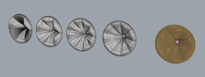
@mabat I managed to get your R-OSSE formula into grasshopper with the correct curvature. Here's a snapshot of the parametric model - more to come as I start to add in some complexity but for now it is looking promising.
Attachments
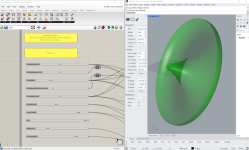
Here's another image that I quickly whipped up that shows the horn being subdivided into different segments, with the segments being able to be pleated or shaped (if that's a good thing or not I literally have no idea - its just geometry to me). In any case, it allows for super fast iteration and testing, which is exciting.
Attachments
- Home
- Loudspeakers
- Multi-Way
- Acoustic Horn Design – The Easy Way (Ath4)