That is, you treat the symptoms and not the cause!I get a good result with additional LDO for PLL supply
Using linear regulator (not necessary LDO) just for PLL - is not enough, you have to do this also for 3.3v and 1v, and after this - to take PLL from this 1v. through RC.
If you do not want high current consumption and heat dissipation in case of all linear regulators, the best way is to use:
1) one linear 3.3 regulator directly from 5v, to XMOS' I/O,
2) switcher from 5v to 1.5-2V
3) one LDO after the switcher, to get 1v. Not PLL only.
4) PLL - through RC.
So you can't prove any changes. Just "I swear!" 🙂Unfortunately I don't have good ADC.
Maybe at least oscilloscope screenshots of power lines and signals?
Alex.
As for my ears core supply with linear reg doesn't improve sound, but in any next xmos modification I'll make linear reg for core too. I can take oscilloscope photos, but even if I prove some difference at screens with linear regulator and switcher at PLL source, then there will probably be people who will say that screenshots are not proof of changes in sound, right ?1) one linear 3.3 regulator directly from 5v, to XMOS' I/O,
2) switcher from 5v to 1.5-2V
3) one LDO after the switcher, to get 1v. Not PLL only.
4) PLL - through RC.
Well, that's what I'm giving advice to people who have the same devices with bad power supply for XMOS, it is not adressed to you. Let people try your variant of power supply for XMOS in your previous post, anyway it will give a good result for this dac.That is, you treat the symptoms and not the cause!
Last edited:
Sure!then there will probably be people who will say that screenshots are not proof of changes in sound, right ?
Only "golden ears" can be the proof!
Alex.
Mmm, I see where this is going to. Nowhere 🙂
I could easily have implemented extra LDO's and also asked this but it was not necessary. Now suddenly they are needed. This way of working is nervous and also leads to never finished/ever changing projects that always sound better after each change.
I could easily have implemented extra LDO's and also asked this but it was not necessary. Now suddenly they are needed. This way of working is nervous and also leads to never finished/ever changing projects that always sound better after each change.
Hope I can ask a question here.
Have replaced the switcher supply in my SMSL DO300 with +=12V supply from a dual bench supply (have ordered a dual linear supply), think the switcher module was producing 2 x 12V supplies and then 2 diodes and 2 caps were used as an inverting charge pump circuit to produce the -12V.
This seems to be the same switcher and circuit used in a lot of the smsl models and wondered if this is the best way to connect the linear +-12 V supply.
It does make a nice improvement to the SQ, even just using a bench supply.
Attachments
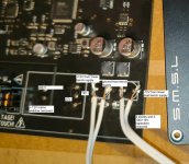
There exist a few versions of that +/- 12V switcher. You can connect a linear PSU like you did but I would make sure stuff is all switched on simultaneously. And the new PSU must of course be able to deliver the same power.
Edit: I see yours has a 230V AC to +/- 12V DC SMPS. The devices I know have a DC xV to +/- 12V DC switcher.
What is the typenumber of that SMPS? It probably delivers a symmetrical + and - 12V. You could have measured that. You still can if it is not thrown away. That is what DMMs are for. If that SMPS delivers +/- 12V you can solder in solder pins in the existing PCB pads and make stuff tidy.
Last edited:
Not golden, just ears. I'm understand what I hear and understand that altor's point is true, but don't understand how it works. Listened again and again and yes, it is better to supply all 0.9(1)V rails from linear regulator, not only PLL. Adjusted switcher to 2V by resistor devider and put LT3045 for 1V after it. Interesting fact, why I encountered with such hearable difference at few XMOS boards. Seems to me it may be a production errors with different values of parts, I'm not exactly sure, but I think I measured the capacity of original cap at PLL pin in SU and it was 0.1uF (with a unknown value coil as filter). Now I can't check it capacity because I threw it out, may be jean-paul can desolder and check it.Sure!
Only "golden ears" can be the proof!
Alex.
Anyway the difference between 0.9V linear reg and switcher power supply is audible. For all users with such devices with XMOS: don't try it if you're not interested in hearing something new
Last edited:
12v is used for analog power supply, so it's no surprise that it's better.the linear +-12 V supply.
It does make a nice improvement to the SQ, even just using a bench supply.
Even when I use a switcher for analog power, I always put LDO after (usually TPS7A39 for OP).
This is not enough, I tried 🙁I measured the capacity of original cap at PLL pin in SU and it was 0.1uF
Even after the linear regulator!
At least 1uF works for me.
Anyway the difference between 0.9V linear reg and switcher power supply is audible. F
That is why I always use linear regulator for 1V XMOS power, after 1.8v switcher.
And RC for PLL.
Alex.

We cut 10x lower frequency noise with 1uF, right ? Why not to use 10uF if there is no money question ?This is not enough
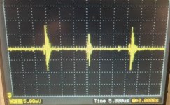
And what do you think about this spikes after good linear regulator at XMOS core supply ? This is caused by regulators reaction for frequently high current surges of cpu core ?
Attachments
Last edited:
thanks, will ensure all switched on at same time.There exist a few versions of that +/- 12V switcher. You can connect a linear PSU like you did but I would make sure stuff is all switched on simultaneously. And the new PSU must of course be able to deliver the same power.
Edit: I see yours has a 230V AC to +/- 12V DC SMPS. The devices I know have a DC xV to +/- 12V DC switcher.
What is the typenumber of that SMPS? It probably delivers a symmetrical + and - 12V. You could have measured that. You still can if it is not thrown away. That is what DMMs are for. If that SMPS delivers +/- 12V you can solder in solder pins in the existing PCB pads and make stuff tidy.
no type no on SMPS, expected to get 24 V across pins if it was +-12 V. Instead say pin 3 was ground then pin 3 to pin 1 was 12V and pin 2 to pin 1 was 12 V, pin 2 to pin 3 had 0 V.
Pin 1 was connected to the +12 V rail.
Pin 3 was connected to the ground.
Pin 2 was connected to the charge pump circuit, was 0 V before the first diode and -12 V the other side of that diode with reference to ground.
thing is those charge pump circuits are known to be noisy so a bit cheeky for the smps to have Ultra Low Noise Power Supply text on it.
Last edited:
OK the very small DC-DC ones by SMSL are symmetrical. Their modus operandi is to create various voltages with several relatively unknown chinese switching ICs.
Once had an SMSL DAC that was new/unopened but it had the wrong adapter with it. To my surprise a message appeared in the display indicating “overvoltage”.
Once had an SMSL DAC that was new/unopened but it had the wrong adapter with it. To my surprise a message appeared in the display indicating “overvoltage”.
Last edited:
Why not? It is possible, a said "at least 1uF".Why not to use 10uF if there is no money question ?
But it should be noted that at frequencies >10 MHz the resistance may be similar.
For 0603 X7R 6.3V capacitor:
@10MHz: 1uF - 20mOhm, 10uF - 18mOhm
@100MHz: 1uf - 150mOhm, 10uf - 120mOhm
There could be many reasons, including radiation to the oscilloscope probe.And what do you think about this spikes after good linear regulator at XMOS core supply ? This is caused by reaction of regulator for frequently high current surges of cpu core ?
Was this picture taken with a spring or a wire + crocodile clip on the ground?
Alex.
forgot to mention, when I opened the DO300 the live wire was connected to the neutral connector and neutral was connected to the live connector, not ideal
So e.g. its not enough to feed the below board by one 3,3V LT3045 regulator? One need to split it up?That is why I always use linear regulator for 1V XMOS power, after 1.8v switcher.
And RC for PLL.
https://www.diyinhk.com/shop/audio-...high-quality-usb-tofrom-i2sdsd-spdif-pcb.html
//
if the live is connected to neutral then the casing could become live without the fuse blowing (fuse is on the live termainal, so a safety issue
It depend of how you will get 1V line.So e.g. its not enough to feed the below board by one 3,3V LT3045 regulator?
LT3045 for XMOS is a big overkill
(Except if it is also used for audio oscillator power, however, it is not the best solution).
Alex.
Last edited:
impedance, of course, |Z|.s >10 MHz the resistance may be similar.
Alex.
A metal casing is therefor connected to PE.if the live is connected to neutral then the casing could become live without the fuse blowing (fuse is on the live termainal, so a safety issue
It occurs to me, well for a longer time really, that I2S to USB conversion and USB to I2S again creates new issues. It is a handicap to have an external DAC. Not a blessing. The created necessity to add what already is there is also not appealing.
I rather skip the whole XMOS shebang and double conversion (with all the associated PSU and other peculiarities) by having a good internal DAC. In the past this has proven itself and maybe it still is superior. Less is usually more. Also we treat any internal DAC to be not OK (while DAC technology has matured) and convince ourselves to need an external upgrade but do we really need that?!
I felt pretty stupid listening to an external XU316/ES9038Q2M DAC while my source has XU316/ES9038Q2M inside 😀
Last edited:
- Home
- Source & Line
- Digital Line Level
- SMSL SU-1 design idea