First, using current sensing feedback is just not working. The proper way is to clamp the sum of VBE, as below, the sum of voltage across R1 and R2 stays constant.
The output stage is using about 500ma in idle.

10KHz, 20Vpk into 8 Ohm, -80dB. (for your reference, the Blameless is about -82dB with my simulation suite)

NFB around the output stage. As the output stage is nested in the Miller cap. The phase margin is lower, but it should not cause any issue.

The output stage is using about 500ma in idle.
10KHz, 20Vpk into 8 Ohm, -80dB. (for your reference, the Blameless is about -82dB with my simulation suite)
NFB around the output stage. As the output stage is nested in the Miller cap. The phase margin is lower, but it should not cause any issue.
Last edited:
Regarding stability. 1st. just use faster devices such as MJL3281A/MJL1302A.
To compensate, just use Miller compensation. It is the most effective way in my opinion.
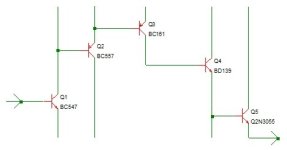
If you nest Darlington topology in the Miller compensation loop, the 2 collectors of the transistors have to be tied together to eliminate a pole.
Like this.
To compensate, just use Miller compensation. It is the most effective way in my opinion.
If you nest Darlington topology in the Miller compensation loop, the 2 collectors of the transistors have to be tied together to eliminate a pole.
Like this.
Last edited:
Look at the MFA1 topology, there s an IPS stage in common emitter driving two transistors in serial wich are bothThe whole theater put forward with the remarkable but regularly introduced sideshows - it must be a joke.
This statement is also nothing more than a pure generalization without specifying the working environment and working conditions. And therefore worthless and even incorrect.
connected as emitter followers, and the output transistor connected as common emitter provide the necessary voltage gain,
so yes, the OS is the actual VAS driven by a two transistors buffer wich itself is driven by the IPS.
An yet you know that 4 bipolar transistors in serial between the input and output are not enough for very good perfs,I beg your pardon?
With the greatest of respect, but I can't go any further into this nonsense - it's too stupid for me.
in a blameless there s 5, each providing a 100 Hfe on average for a grand total of 10^10 combined current gain.
The missing Limiter, the simple one as a lifeguard.
How much bias should I use for the output stage?
1.12 Ampere (dc)
as Iq
for 20W(8Ohm) !

(...) a grand total of 10^10 total current gain.
I_out / I_in = current gain (of the entire circuit)
2.24A / [(Vout/ voltage gain) / r_input]
In our case, this is around 24.000, regardless of which eye wash lotion is used.
---> Imax * dynamic input resistance ---> divided by the required input amplitude ===> current gain
Do you mean BETA, as a multiplication of ..?
End of communication,
HBt.
for very good perfs,
in a blameless there s 5, each providing a 100 Hfe on average for a grand total of 10^10 total current gain.
100 ^5 = 10 ^10
100 * 100 * 100 * 100 * 100 = 10000000000 HFE
YOU are all playing window dressing - that is dishonest! And that's why I'm out of this number.
Generaly it is implemented this way, notice that the total gain is the same, and also, there s two common emitters
and three common collector, with 4 transistors you ll still have two as common emitters, like in the MFA1 or a blameless
without VAS enhancement, as two voltage gain stages are necessary given the low output amplitude of the IPS.
and three common collector, with 4 transistors you ll still have two as common emitters, like in the MFA1 or a blameless
without VAS enhancement, as two voltage gain stages are necessary given the low output amplitude of the IPS.
Attachments
Yes, we can, but I choose not at least in this thread. Otherwise, everything converges into blameless design. I have symmetrical blameless design in another thread on this forum.Generaly it is implemented this way, notice that the total gain is the same, and also, there s two common emitters
Two DC voltage regulators that compete with each other - and thus lead to the desired quiescent current, the praised class A operation.
The two halves of the circuit compete and each of the two tries to gain the upper hand, i.e. any extremely pimped A1 version can also tip over.

As soon as you couple both halves together, you no longer only have to solve the well-known safety issue of an HF oscillation tendency, but also have to precisely control (and adjust) the DC control behavior.
Any attempt at modification (i.e. the desire for improvement) can backfire. I would like to expressly warn against this at this point. Unfortunately, the mirror image must also correspond to the "other me" in all parameters. It just has to be a 100% complementary structure.
If we now slavishly pursue the demand for the utopian THD, then the problems chase each other; once one is eliminated, the other is happy (and gets up to mischief). For this reason alone, Bernhard will never bring the present design to maturity, let alone market his -240dB thd dream amplifier.
#
The really stupid thing is that we simply have to say goodbye to dream THD values. And at the same time, even today you can't solve a single problem in the simulator alone, i.e. we need various experimental setups.
If the A1 case was as easy to improve as we might all wish, Musical Fidelity would certainly have done so already. The topology poses a challenge. I had hoped we would tackle them together, but I'm probably the only crazy person who has already simulated 4 hours this morning.
HBt.
The two halves of the circuit compete and each of the two tries to gain the upper hand, i.e. any extremely pimped A1 version can also tip over.
As soon as you couple both halves together, you no longer only have to solve the well-known safety issue of an HF oscillation tendency, but also have to precisely control (and adjust) the DC control behavior.
Any attempt at modification (i.e. the desire for improvement) can backfire. I would like to expressly warn against this at this point. Unfortunately, the mirror image must also correspond to the "other me" in all parameters. It just has to be a 100% complementary structure.
If we now slavishly pursue the demand for the utopian THD, then the problems chase each other; once one is eliminated, the other is happy (and gets up to mischief). For this reason alone, Bernhard will never bring the present design to maturity, let alone market his -240dB thd dream amplifier.
#
The really stupid thing is that we simply have to say goodbye to dream THD values. And at the same time, even today you can't solve a single problem in the simulator alone, i.e. we need various experimental setups.
If the A1 case was as easy to improve as we might all wish, Musical Fidelity would certainly have done so already. The topology poses a challenge. I had hoped we would tackle them together, but I'm probably the only crazy person who has already simulated 4 hours this morning.
HBt.
I want to say not to emphasise on THD too much. As long as it is be low a certain point, such as -70dB (@10K), or even -60dB, it should not be 1st priority.The really stupid thing is that we simply have to say goodbye to dream THD values. And at the same time, even today you can't solve a single problem in the simulator alone, i.e. we need various experimental setups.
A blameless 3055/2955 design. 30dB NFB over 10KHz. The THD is about -73dB @10KHz. You don't have to beat blameless to be successful.
For DIY, the circuit has to be attractive. A1 has it. The 2nd, it should be relative easy to build.
Bernhard will never bring the present design to maturity
I've got nothing to do with your vas-output-amplifier, other than doing some simulations.
The vas-output-amp is MF, Tim de Paravicini, not me. I can also simulate all by myself 😉.I've got nothing to do with your vas-output-amplifier, other than doing some simulations.
The only question that has bothered me since time immemorial is: can we improve the design slightly? The really big thing will go down the drain - no matter how beautifully MC12 paints the world for us.
the demand for the utopian THD
What "utopian" ? Something better than the -70dB of the A1 is far from utopian.
I_out / I_in = current gain (of the entire circuit)
2.24A / [(Vout/ voltage gain) / r_input]
In our case, this is around 24.000, regardless of which eye wash lotion is used.
---> Imax * dynamic input resistance ---> divided by the required input amplitude ===> current gain
Your brave calculation is for the amplifier closed loop, right ?
Thesis
In A1, the transistor marked in yellow is nothing more than an impedance converter. Between the negative feedback node B and the output node A.
An A1 must not be regarded as an IPS with differential amplifier on the input side, i.e. a balanced stage with a current mirror as collector load is counterproductive, in particular because of the DC voltage regulator actually present, whose reference point we modulate ac-like.
When viewed as an LPT, the optimization, especially the goal of the later powerful ac-global-voltage-feedback, is a mistake.
under full load, full scale, max swing ...
In A1, the transistor marked in yellow is nothing more than an impedance converter. Between the negative feedback node B and the output node A.
An A1 must not be regarded as an IPS with differential amplifier on the input side, i.e. a balanced stage with a current mirror as collector load is counterproductive, in particular because of the DC voltage regulator actually present, whose reference point we modulate ac-like.
When viewed as an LPT, the optimization, especially the goal of the later powerful ac-global-voltage-feedback, is a mistake.
original A1 has -66dB thd!What "utopian" ? Something better than the -70dB of the A1 is far from utopian.
- your standard is, always better -126dB thd
- my motto, no worse than -90.5dB thd
under full load, full scale, max swing ...
Attachments

I love your rhetorical questions. Answer: but yes, darling.Your brave calculation is for the amplifier closed loop, right ?
Please don't play any more games, dear Bernhard, otherwise I'll drop by for a walk in Munich (then we can really get to grips with the electronics).
Open loop:
voltage gain for one half alone is greater than 100000. Current gain -> 618421053, do you think that might be enough? The correct answer to “this rhetorical question” is: Yes!
@Bernhard,
"bist Du ein Troll?" Are you a troll? I only want to deal with the A1 and not with you. If you can increase the OLG (voltage not current) of the original A1 in such a way that the entire system remains safe for negative feedback, then I would be happy to listen to you. If you just want to make a fuss, please do it somewhere else. Thank you.
greetings,
HBt.
- Home
- Amplifiers
- Solid State
- An A1 descendant - a relentless analysis