On the last preamp, it fixed noise by removing cap between vs+- and using each to gnd.
It will be commond ground, but conected externaly via wire, on the last preamp I didn't figure how to run ground from vs+ capacitor to vs- capacitor to avoid signal circutry and I ended up running hard wire in U shape above the circutry and result is good. That way it is shorter than running it all around on the board and has more clearance versus running jumper just above the signal circutry...
I have signal and power capacitors grounds seperated, jointed at power supply.
I'm open to suggestions, I would like to expand my layout making skills.
For now I just know that shorter the traces, the better & avoiding putting any signal close to power lines.
One “sees” the resonant frequency of the box with an impedance measurement. It’s the valley right in between two peaks (one far below useability and one above). Put a resistor in series (10 ohm), and do a sine sweep. Look for the voltage minimum (regular hand held DMM is fine for this).I cant see the resonant frequency of the box, driver and xmax are just too small.
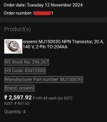
Not much, $36.5. But this is the second time i'm buying MJ15003G, so it's $73 total spending within a month & i already hve a large stock of other components as well. I don't belong to a rich family & i lost my father many years ago (But he left such i can live my life comfortably, i miss him everyday, nothing can fill such void). So i hve to think about other needs as well. Btw i didn't post the price tag intentionally, i just took a screenshot to share the joy.
Last edited:
When I see something that 2,500 of something it just makes me wonder. Just needed a sense of scale. $2500 for a few transistors, sheet of plywood or loaf of bread would require rethinking audio entirely, even whether or not it’s worth it to go on living….. But I can see it happening in our lifetime, too.
Hey man, just make something for her.I'm also thanking me for the care i'm taking for my hobby. Placed another other for MJ15003G
I'm doing all of this because later my would be wife will kill me if i continue such spending, i fear. She is studying law
Anyway, now i have all power semis for my wish lists. No need to buy more to3 now.
View attachment 1379965
This project is for my better half, as it will be going in the kitchen.
"Your just doing your stuff" changes into "Aaaw, your thinkering so much for me, it sounds good enought for me, you don't need to do better"....
Maybee try with record players, it's a style, mine loves them.
And put some quality headphones on her head. 🙂
When we got together, mine wasn't happy about 15 speakers in my room either...
Ha ha ha... Definitely, sure i'll do something for her. She is a beautiful women with a golden heart. She is studying law only because of me & there is a reason for it (no, i'm not a criminal & got no imprisonment). We didn't speak to each other for nearly 12 years! Would you believe me? It's a sad but beautiful love story. Now it's time to marry & bring her home.
Anyway, we should back to the thread subject. Please continue...
Regards
Anyway, we should back to the thread subject. Please continue...
Regards
I was thinking the same thing when I saw.When I see something that 2,500 of something it just makes me wonder. Just needed a sense of scale. $2500 for a few transistors, sheet of plywood or loaf of bread would require rethinking audio entirely, even whether or not it’s worth it to go on living….. But I can see it happening in our lifetime, too.
I`m trying to figure out values for baffle step compensation circuit. My native language is not English and I have a hard time finding out what baffle and baffle width is...
Is baffle a face of the box where speaker is mounted?
From what I found frequency is determined with this formula:
fb = 115 / Bw (baffle width)
...so if my box will be for example 20cm wide:
115 / 0.2 = 575 hz
is this correct?
Height doesn`t matter at all from what I had read?
Is baffle width internal or external dimension of the boxes face?
Can I use this info to build it?
link
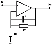
@wg_ski : Tis circuit has one resistor less (input not counted), than the one you had drawn for me. Is this ok?

Last edited:
Baffle is the external dimension. 600–ish Hz is about right. I use that figure a lot. No, the one resistor less won’t work. You want something that cuts the resistor in half as the frequency goes up, not eliminate it entirely. To trim that boost, just make the resistor That’s in parallel with the caps pot.
For high gain values, make those resistors equal to get +6dB boost. That annoying “+1” to the gain in non inverting configuration causes the boost to drop at low gain settings, but resistors can be adjusted to give a 2:1 gain spread. To eliminate that little annoyance, just use inverting configuration. If you use Baxandall tone controls you are stuck inverting, inverting back makes sense anyway. Another possibility is to do the shelving boost in the power stage where the gain is high enough to ignore the “+1”. No stability issue, because the gain is unchanged at high frequency. It will go up at low frequency, but only by 6 dB.
For high gain values, make those resistors equal to get +6dB boost. That annoying “+1” to the gain in non inverting configuration causes the boost to drop at low gain settings, but resistors can be adjusted to give a 2:1 gain spread. To eliminate that little annoyance, just use inverting configuration. If you use Baxandall tone controls you are stuck inverting, inverting back makes sense anyway. Another possibility is to do the shelving boost in the power stage where the gain is high enough to ignore the “+1”. No stability issue, because the gain is unchanged at high frequency. It will go up at low frequency, but only by 6 dB.
Does it matter if phase is shifted before entering tone control stage?
I have other half of second Ne5532 unused.
I was thinking if I could do inverting baffle compensation and invert it back at the end with unused opamp?
Or I can start over with layout and use first NE for inverting baffle compensation, followed by inverting buffer (if I could use it as sallen-key 30hz HPF, it would be great) and then leave tone control as is.
Last edited:
- Home
- Amplifiers
- Solid State
- Amplifier suggestion for old 3w speaker


