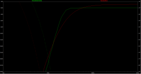
Log = decade. Decades are equally spaced. Then the plots look more familiar and they are easy to really compare.
The initial slope (before final roll off) depends on the Q values chosen for the filter. One was from a non audio application, where shallower may have been preferred. In that one, both Q’s are the same. You may or may not actually want this. One can also design it for peaking before final roll off - some receiver manufacturers did that, having it as an option for the use of small speakers.
The initial slope (before final roll off) depends on the Q values chosen for the filter. One was from a non audio application, where shallower may have been preferred. In that one, both Q’s are the same. You may or may not actually want this. One can also design it for peaking before final roll off - some receiver manufacturers did that, having it as an option for the use of small speakers.
Ok, thank you. When I get home, I will dive into theory and formulas and hopefuly I will be able to come up with modifications.
I was playing with different capacitors, but it didn't affect Q too much.
I think that slope of second filter is different, because I left it's output floating -no external impedance...
I was playing with different capacitors, but it didn't affect Q too much.
I think that slope of second filter is different, because I left it's output floating -no external impedance...
Higher Q’s require higher gain in the op amp. Strapped as a follower, the Q that can be achieved is limited, but the circuit is relatively insensitive. Set for a gain >3, and you sneeze on it and the response changes. When you want Q>2, this is not the circuit you want to use. But it never is in these applications.
Ok. But higher gain, more sensitivity also means more pickup of unwanted noise I suppose?
I will experiment, but what I like about what we did so far is good resistance to noise. I remember some high gain preamps that I had built before were very sensitive to everything around it and as I have MCU and stepper motor in my project, I would like to "get by" with less sensitive circutry.
It will be interesting to see how curve will look when I add tone control to it.
I guess there is quality loss if you take away too much and add it back in later stage vs not taking away and not adding afterward?
To design it for peeking before roll-off...can one design this in the same stage or would this be the narrow bandpass in following stage?
I`m reading a book... basics and so on and on page 44 here comes the "Differentiator with stop"... It finaly makes sense and I have needed formulas.
Ok...
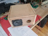
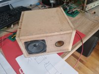
I had built the speaker box, my plan is to simulate various filters with pc EQ, listen & compare to decide what I will make.
But it has realy nice sound as is.
Probably I wont need 6db of baffle compensation, more like 3db... if any.
Once I put wooden mesh infront of it, I will be probably be boosting highs. Or if I'm lucky loss of highs will compensate for the baffle.

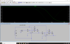
I'm doing decade-log on both simulations, but I don't know why it's scalling graph differently. Will sort it out and compare.Sallen-key isn’t a type of alignment, it is a type of active filter. Both are Sallen-key filters. One may be of unknown alignment…. Both need to be on log scales to compare anyway.
May I ask... can too much low end make artificial sounds at higher frequencies with full range speakers?
It's like when there are lows playing and mids/ highs come in I can hear a sound that I can best describe as someone would squeze plastic foil in hand... just for a split second, then it stops...
I had the same problem with my late 70s 3way Pioneer speakers and never could pinpoint a problem.
I started to think that I was "making it up" as I could never reproduce the problem intentionaly... however speaker replacement solved it after all...
Too much low end for for the driver can result in very high, somewhat nasty distortion when you hit the mechanical limits of the driver. It’s fairly gentle when you just drive the coil out of the magnet gap. Go further and it gets particularly nasty, sounding like farts.
This is the reason modern tiny speakers are tuned low, with crazy amounts of x-max and 1-watt sensitivities down in the 70’s.
This is the reason modern tiny speakers are tuned low, with crazy amounts of x-max and 1-watt sensitivities down in the 70’s.
Ok, thank you.
I will have to do some listening to decide how high I will go with HPF...
It sounds much better than it did with stock radio that speakers came with, but HPF was obviously higher.
The box however lifted the lows nicely. I don't know if it's the thicker wood, placement of driver & port, or bigger depth of the box (and shorter width -same volume), but it is better.
I did find the specs for the radio and it's 5wRms... advertised at the store as 2x30w max....
I might need to lower power supply back down (will see after measurements).
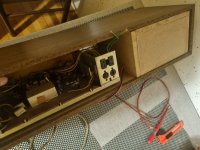
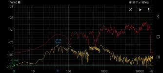
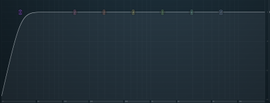
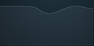
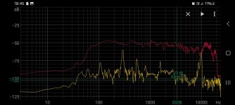


I measured frequency response with android phone (internal mic) for fun, lucky try...
I compared the result with other speakers and results appeared to be in range.
I designed eq curve on pc and did the measurement, second measurement shows improvement,
Also I tweaked everything a bit by ear and make things more subtile as speaker couldn˙t handle lower frequency range on some songs to well.
It sounds nice via pc eq.
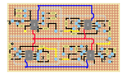
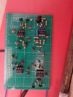
I must still check eveything once again just to be sure, but I`m building this... I hope that it will work.
Almost done. Final stage is missing, because seller gave me wrong capacitors.
I had tryed it anyway, the last stage only lowers the highs (+13kHz) for around 1.5dB.
It sounds wonderful, using gradual slope at lows boost was the correct choice. Now it can play loud and still breath.
It sounds like much bigger speaker, even the whole size of the radio leaves you confused, because it still looks way smaller than it sounds.

Last edited:
Well, the end result here bears very little resemblance to what you started to modify, but I bet you learned a lot. Now that you learned the basics about filtering and how to dial things in, you are about 110% further ahead of where most people who want to go “build a 3 way speaker, using a pre-built crossover” are. For when you go to build your next bigger, badder project. That red curve looks pretty nice for just a cheap full range speaker - which now does not have that blaring, screechy, “in your face” midrange thats’s pretty typical. Yeah, it would be “nice” to have a bass bump down around 60, but as you’ve seen that comes at the cost of everything else when the wattage is low and the driver can’t move a lot of air. A listenable system is a better compromise.
I had completed last stage.
Yes, project went completely the other way, but I like it. Now it sounds nice on various genres, modern & old.
Some of the sound character stayed, partly due to bass boost. I would have to do some testing & measurements, but I believe that original (found out it`s plastic and not wooden) speaker grill shapes the sound in some weird way.
Tuner has some bass boost -that typical late 90s sound... probably in the range bellow 100hz.
I had connected amplifier to the tuner for the first time earlier today and it matches nicely, it extends that low end a bit.
I had also tried to play with pc eq on top of preamp and it shows that this is the optimum eq curve -it needs no further corrections.
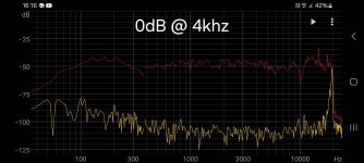
This is the response with the actual preamp:
I must do some simulations to see the outcome, but I will probably use stereo volume pot and tie ends of second half together -that way it will get low toward both ends and I will use that to lower the lows when playing at low volume for clarity and when playing at high volumes to avoid distortion.
I will either enable 16khz filter on tuner or drop highs a bit with a preamp, because radio static is realy audible.
Yes, project went completely the other way, but I like it. Now it sounds nice on various genres, modern & old.
Some of the sound character stayed, partly due to bass boost. I would have to do some testing & measurements, but I believe that original (found out it`s plastic and not wooden) speaker grill shapes the sound in some weird way.
Tuner has some bass boost -that typical late 90s sound... probably in the range bellow 100hz.
I had connected amplifier to the tuner for the first time earlier today and it matches nicely, it extends that low end a bit.
I had also tried to play with pc eq on top of preamp and it shows that this is the optimum eq curve -it needs no further corrections.
This is the response with the actual preamp:

I must do some simulations to see the outcome, but I will probably use stereo volume pot and tie ends of second half together -that way it will get low toward both ends and I will use that to lower the lows when playing at low volume for clarity and when playing at high volumes to avoid distortion.
I will either enable 16khz filter on tuner or drop highs a bit with a preamp, because radio static is realy audible.
- Home
- Amplifiers
- Solid State
- Amplifier suggestion for old 3w speaker
