Ok. So it doesn't matter, whatever stage I have, whatever filter, etc... if signal that gets to it is phase shifted or not... characteristics will stay the same?
Also is there a fule of thumb on when buffer is needed between two stages, so for example one filter doesn't affect the other?
And when I want a filter HPF or LPF in the audible range, is it better to put it at the start of the chain, so the whole chain doesn't have to process what I don't need at the end anyway, or is it better to put it last, so if circutry itself generates unwanted signals that said filter would block, it blocks them.
For example like with first tone control we did, it was generating about 300khz noise, LPF would block that if it was placed after, but not if it was placed before...
I believe that less stages there is the better right?
So one can strategicaly place the stages to avoid the need for another stage...
Last edited:
There are other ways to build and synthesize filters - S-K is just “pressing the easy button”. I’ve built them using single transistor stages (an input-bootstrapped emitter follower works pretty much the same as a follower-strapped op amp, and tubes configured as cathode followers work too).
The textbook examples and on-line calculators usually do just 2nd order filters, as one block makes one “biquad”. You specify cutoff frequency and Q. For 2nd oder butterworth it’s .707, and for linkwitz-Riley it’s 0.5. All higher (even) order filters can be broken down into products of biquads, each with an associated Q. Any filter handbook will tell you what they need to be for common alignments. Odd order filters just have an additional single time constant also applied. A 4th order filter just takes a whole 5532 to make. In theory any op amp of sufficient gain-bandwidth can be used, but S-K filters can often end up with feedback impedances that are hard to drive. 5532’s have a lot of drive capability and decently low noise.
The textbook examples and on-line calculators usually do just 2nd order filters, as one block makes one “biquad”. You specify cutoff frequency and Q. For 2nd oder butterworth it’s .707, and for linkwitz-Riley it’s 0.5. All higher (even) order filters can be broken down into products of biquads, each with an associated Q. Any filter handbook will tell you what they need to be for common alignments. Odd order filters just have an additional single time constant also applied. A 4th order filter just takes a whole 5532 to make. In theory any op amp of sufficient gain-bandwidth can be used, but S-K filters can often end up with feedback impedances that are hard to drive. 5532’s have a lot of drive capability and decently low noise.
Ok, so it's a compromise.
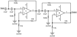
Is this 4th order sallen-key HPF good?
It says it has 20hz corner frequency, -24dB / octave.

From what I had found, it is not to common for opams to introduce noise bellow 20hz, so I would say it is better to use 20hz HPF at the start of the chain. Some modern music tends to have supidly strong bottom end (REBASSED, BASS BOOSTED versions of music, etc) and this is another reason why I would put HPF at the start.
Would you say that my choice is correct here?
Is this 4th order sallen-key HPF good?
It says it has 20hz corner frequency, -24dB / octave.

From what I had found, it is not to common for opams to introduce noise bellow 20hz, so I would say it is better to use 20hz HPF at the start of the chain. Some modern music tends to have supidly strong bottom end (REBASSED, BASS BOOSTED versions of music, etc) and this is another reason why I would put HPF at the start.
Would you say that my choice is correct here?
Yes, about putting it in front of the chain. To go to 40 Hz, all one has to do is cut the cap values in half. For 50 Hz, go to 2/5. 10 nF is in between enough where it would work fine, you probably don’t want to hit that little speaker too hard below 40 Hz.
Whether it was calculated right, Id have to hand calculate the fo and Q, but since it was a published circuit it’s probably at least ball park if not spot on. R-C values look in the right ballpark for frequency. I’m used to using the unity gain version, which requires a 2:1 capacitor ratio - but that’s not the only way to do it.
Whether it was calculated right, Id have to hand calculate the fo and Q, but since it was a published circuit it’s probably at least ball park if not spot on. R-C values look in the right ballpark for frequency. I’m used to using the unity gain version, which requires a 2:1 capacitor ratio - but that’s not the only way to do it.
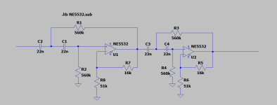
Thank you. I will try to set LT Spice together for simulation.
I wanted to learn on how to calculate values, but found out that I would need a long conversation with books before I can do it.
I wanted to learn on how to calculate values, but found out that I would need a long conversation with books before I can do it.
I saw long formulas with greek alpabhet and got scared, will dive in.
I will check Elliots site.
What is an op amp app note? // edit: ok, I found out, it's documentation, this will be handy.
I will check Elliots site.
What is an op amp app note? // edit: ok, I found out, it's documentation, this will be handy.
Oh, thank you. I got scared away to fast it seems. I never liked math too much, but anyway I enjoyed physics classes. I should manage.
May I ask, do u use LT Spice and have NE5532 imported?
I want to make sure to have a good model.
This is what I had found for universal opamp2 method:
SpiceModel: level.3a
Value2: Avol=50k GBW=7.2Meg Slew=9Meg
SpiceLine: ilimit=38m rail=1.5 Vos=0 phimargin=60
SpiceLine2: en=5n enk=40 in=0.7 ink=150 Rin=50k
The other method of importing .sub file over the opamp2, I cannot figure out, probably something in GUI got changed over the years, because in
"Step 4: Add the spice directive to the schematic using the .op. Add “.lib LM741.sub” to the schematic." I can`t find ".op" anywhere...
"
Last edited:
Don’t over think things for something this simple. You don't need a high level of detail in the model. For something like this I just use a VCVS, with a specified 3dB dominant pole frequency and high DC gain that are something like a real op amp. “Ideal op amp” assumptions are even good enough for these purposes. All we’re really looking to do here is dial in a frequency response to complement a small speaker, not determine large signal frequency limitations, predict noise or distortion, or look at supply current over temperature.
Ok,
But I had just managed to import it... I installed older version and found the .op button.
Hopefuly I won`t get to sleepy, my goal today is to have the HPF simulation running.
But I had just managed to import it... I installed older version and found the .op button.
Hopefuly I won`t get to sleepy, my goal today is to have the HPF simulation running.
Last edited:
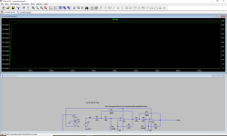
Everything looks a little funny. You should be getting a little bit of gain, not 190 dB of loss. And you really want to do a log frequency sweep, from 0.1 Hz to maybe 1 KHz, with say 10 points per decade. It will “look” like a Bode plot then.
To get an idea what it “should” look like use an ideal voltage controlled voltage source for the op amp. Set input impedance to some high value (10 meg or so), Gain to maybe 50k, and output impedance to 10 ohms. If there is an easy way to specify a -3dB point, set it to 100 Hz. That will make a linear approximation to an op amp with a GBW of 5 MHz and not have to jack with power supplies, DC bias points, or other mostly irrelevant things. A more realistic model should give you something close, just differing in what happens well above the audio band. If not something is wrong.
To get an idea what it “should” look like use an ideal voltage controlled voltage source for the op amp. Set input impedance to some high value (10 meg or so), Gain to maybe 50k, and output impedance to 10 ohms. If there is an easy way to specify a -3dB point, set it to 100 Hz. That will make a linear approximation to an op amp with a GBW of 5 MHz and not have to jack with power supplies, DC bias points, or other mostly irrelevant things. A more realistic model should give you something close, just differing in what happens well above the audio band. If not something is wrong.
Yes, I don`t know what happened. I choosed new universal opamp2 and changed only Rin to 10meg.
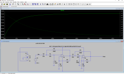
Now it`s good. This is with 10nF caps:

I must find a legend of parametres to dial it better.
log sweep = decade sweep?
I can`t find log option...
And also I don`t know why slope is more sharp on first preamp (blue)...

Now it`s good. This is with 10nF caps:

I must find a legend of parametres to dial it better.
log sweep = decade sweep?
I can`t find log option...
And also I don`t know why slope is more sharp on first preamp (blue)...

- Home
- Amplifiers
- Solid State
- Amplifier suggestion for old 3w speaker


