I would also focus on the loudspeaker and the housing: There is a lot of room for improvement in terms of sound. We have a wooden grille here, a paper driver in a sheet metal cage, screwed directly to a wooden box.
If the original circuit still works, I would also use it: simplify it at best, in the direction of #21
If the original circuit still works, I would also use it: simplify it at best, in the direction of #21

Will try TDA2003 first, as it is the simplest.
What do you think could be done to the housing? I would like to keep the grille for the aesthetics, back is partly open (perforated hardboard), also under the pcb there is an "service cutout square" about 20x20cm, covered by hardboard and I believe that this adds alot of lows.
Speaker I want to keep. So I don`t see much to improve here.
Keep in mind tda2003 (car amp for low voltages) is not the same as tda2030 (better specs but needs higher rails). Tda2050 is the slightly increased power version of 2030, available from reichelt.deThis "testing circuit" from the datasheet is a bit different from what @lineup posted...
6283 is quite reliable, good sound quality in our FM radios, good vocals and bass in the FM radios with bass and treble controls, usually 3 or 4 inch speaker on top, sheet metal cabinet.
TDA 2030 is my preference over 2003, at about +/-9V, clean sound.
Fussy people use the circuits with Keltron (Sprague licensee) capacitors, they are better than Chinese capacitors.
The frequency response may be adjustable...
Also, my friend's kids use their cellphones to send music to his car radio over Bluetooth, available in the FM modules mentioned above.
But it all depends on whethe you want to listen to AM or FM radio, of course.
TDA2003 is not the same thing as a TDA2030, the latter has much better perfs as well as supply voltage capability.
There s also the TDA2040 wich is a more powerfull version of the TDA2030 but seems to me that only the TDA2030
is still available from ST Micro.
As said it should be connected in inverting mode, this way it can be connected to R241 on the schematic and will replace
T205/206/207/208 but not T204, hence the original tone control will be unchanged.
Whether to use 2003 or 2030 depends on the supply voltage. If you are under 18 volts, use 2003. If over, use 2030. The 2003 was optimized for low voltage operation - and pretty much nothing else is. Unless you go discrete.
The original tone controls are probably the reason you liked the sound of this thing in the first place, and they ARE active. It’s in the feedback loop of the power amp section. I’d put them elsewhere, then ANY power amp of sufficient output can be used. Even when the bass and treble are turned ALL THE WAY DOWN there is still boost going on. There is just more with them turned up. I’ve analyzed the circuit and it’s a smiley face from Hell. That speaker, poorly baffled, without it is going to sound like a tuna fish can.
The original tone controls are probably the reason you liked the sound of this thing in the first place, and they ARE active. It’s in the feedback loop of the power amp section. I’d put them elsewhere, then ANY power amp of sufficient output can be used. Even when the bass and treble are turned ALL THE WAY DOWN there is still boost going on. There is just more with them turned up. I’ve analyzed the circuit and it’s a smiley face from Hell. That speaker, poorly baffled, without it is going to sound like a tuna fish can.
2030 it is...6283 is quite reliable, good sound quality in our FM radios, good vocals and bass in the FM radios with bass and treble controls, usually 3 or 4 inch speaker on top, sheet metal cabinet.
TDA 2030 is my preference over 2003, at about +/-9V, clean sound.
Fussy people use the circuits with Keltron (Sprague licensee) capacitors, they are better than Chinese capacitors.
The frequency response may be adjustable...
Also, my friend's kids use their cellphones to send music to his car radio over Bluetooth, available in the FM modules mentioned above.
But it all depends on whethe you want to listen to AM or FM radio, of course.
I`m sorry, but "sheet metal cabinet" and "good sound quality" don`t work together in my head.
Also I went thru hell with "FM modules, bluetooth modules & usb player modules" before finding SONY TUX032 module from old car radio and I went to great extent of C++ coding to make it work via I2c, because there really is a big big difference.
FM reception here is not the best in last years, and such modules were really noisy, some even emitting their own digital noises. The only other module that did good was TEF6686.
Other modules with tuner ICs such as TEAxxxx, RDAxxxx, TDAxxxx had disappointing SNR.
As for bluetooth, I can hear the whole data conversation between the phone and the module, together with the music.
I had tryed such modules before in various projects, but the quality is just not there.
I think that my best bet is to use 8-0-8 transformer as you suggested earlyer. That would give me 12,6v for other part of the project and 25,2v for the amplifier, which would then be TDA2030.Whether to use 2003 or 2030 depends on the supply voltage. If you are under 18 volts, use 2003. If over, use 2030. The 2003 was optimized for low voltage operation - and pretty much nothing else is. Unless you go discrete.
The original tone controls are probably the reason you liked the sound of this thing in the first place, and they ARE active. It’s in the feedback loop of the power amp section. I’d put them elsewhere, then ANY power amp of sufficient output can be used. Even when the bass and treble are turned ALL THE WAY DOWN there is still boost going on. There is just more with them turned up. I’ve analyzed the circuit and it’s a smiley face from Hell. That speaker, poorly baffled, without it is going to sound like a tuna fish can.
Yeah, I can understand what you are saying. The company back in the day was known for making their product sound decent for as cheap as one could possibly imagine, so they were definitely turning things around as much as they could.
This in the first place is the reason of my concern, that`s why I didn`t just look in the drawer for some generic amp.

Here I have deleted everything but tone controls (I think), input of TDA2030 to R241....
R248 must stay or not?
Anything else?
Also then if possible, I would keep the power transformer, it would come handy, because it has winding for illumination bulbs that I would like to keep halogen.
Last edited:
Gain is high enough that it will be stable, regardless of position of the controls. Don’t omit the 200 ohm to ground if the TDA2003 is used. It mitigates crossover distortion. Also wastes DC power, but nobody cared about that in car radio application. The 2030 should work too. If you use 2003, run the supply up to 18V. If you use 2030, run it up to 20-22, just to get the same power. And it will need a heat sink.
I’d prefer to do any tone shaping in a separate block, ahead of a flat amplifier - but if you want to press the Easy Button, this is it…..
I’d prefer to do any tone shaping in a separate block, ahead of a flat amplifier - but if you want to press the Easy Button, this is it…..
Good, thanks.
If I would use either 2003 or 2030 depends only on the power supply then. I`m not too familfiar with power supplyes other than full wave rectified either single or +- rail.
Original looks to me as two half wave rectified rails are joined together so, they somehow get 15,5v. Can I keep this design?
I like that variant, because it will help me save space. I will have a "good time" doing arrangement of components in the radio as I have dc stepper, tuner, bluetooth, MCU, etc...
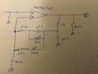
Output coupling capacitor can be 4700uF?Those tone controls are part of the feedback loop that went all the way around the amp from speaker out to the emitter of T204. The power amp included T204. To duplicate the original amplifier one must:
What would be the value of resistor going from in put to gnd? around 50k?
And should I add input coupling capacitor? around 10uF I suppose?
The original power supply is just the positive half of a split supply. What to do depends on the voltages you need, and the transformer(s) available.
Output cap needs to be something “big”. Just make it bigger than what was there and all is good. If you have a 2200, use it. Resistor from + input to ground isn’t critical. Just use the one from the data sheet of the chip you use. Input cap, 10 uF is fine. You probably have some.
If using a single supply with a split supply chip, use a 10k+10k voltage divider to make the bias reference, and bypass the lower cap with 100 uF. That will keep the 1/2Vcc reference noise and hum free. Hang the input resistor to that point. Then capacitor-couple the resistor from minus input to ground to keep the DC gain at 1. 100 uF is enough, more can’t hurt.
Last edited:
Ok... if doing single rail version can I just connect Vs- to gnd and Vs+ to +? and if dual rail version Vs - to - (negative output) and Vs+ to +?
Correct on rail connections. The input bias circuit just needs to be adjusted according to which is used, and of course an output cap is required on a single supply. It’s a good thing actually. A misconnection could result in the output voltage sticking to the rail. The cap prevents that from killing the speaker. You can correct the mistake, and move on with no harm done.
Ok, thank you.
Only thing I still don`t understand is the Input bias circuit... It needs to be adjusted occording to what? I can put 50k resistor if I need 50k input impedance and so on?
If dual rail supply is used, do I also need to tie another resistor to vss+? and equal resistor to vss- instead of gnd?
Only thing I still don`t understand is the Input bias circuit... It needs to be adjusted occording to what? I can put 50k resistor if I need 50k input impedance and so on?
If dual rail supply is used, do I also need to tie another resistor to vss+? and equal resistor to vss- instead of gnd?
- Home
- Amplifiers
- Solid State
- Amplifier suggestion for old 3w speaker