Let's play dumb and ask: what is a steam engine? - "Da stellen wir uns doch einmal ganz dumm und fragen: was ist eine Dampfmaschine?" [die Feuerzangenbowle]You should swap C11,C12
Why? I think you, dear Bucks Bunny, should also explain the why to the dear readers of this forum, i.e. explain the effect of your proposal in a comprehensive and understandable way.
☕
greetings,
HBt.

my lifetime is also limited
That's why we have REW. It takes like 30 seconds to do a full distortion measurement. (Maybe 5 minutes if you include setting up). This is not 1979 anymore. 🙂
Although normally I do not reply to postings with that pompous attitude, I will give my explanation.Let's play dumb and ask: what is a steam engine? - "Da stellen wir uns doch einmal ganz dumm und fragen: was ist eine Dampfmaschine?" [die Feuerzangenbowle]
Why? I think you, dear Bucks Bunny, should also explain the why to the dear readers of this forum, i.e. explain the effect of your proposal in a comprehensive and understandable way.
☕
I suppose you want a frequency compensated voltage divider.
This works in the same manner as frequency compensated 1:10 dividers inside scope probes.
The principle boils down to the impedance ratio of R1:R2 equals the impedance ratio of paralled C1:C2
With Zcap = 1 / 2 * pi * f * cap the imoedance is INVERSE proportional to the cap value.
Thus the cap with the smaller cap is paralleled to the resistor with the bigger impedance.
Agreed?
In all clarity:Although normally I do not reply to postings with that pompous attitude,
Dear Bucks Bunny,
I absolutely do not want to get involved in your games!
This was the original intention, as I recently wrote here.I will give my explanation.
I suppose you want a frequency compensated voltage divider.
This works in the same manner as frequency compensated 1:10 dividers inside scope probes.
Absolutely correct!
The principle boils down to the impedance ratio of R1:R2 equals the impedance ratio of paralled C1:C2
With Zcap = 1 / 2 * pi * f * cap the imoedance is INVERSE proportional to the cap value.
Thus the cap with the smaller cap is paralleled to the resistor with the bigger impedance.
And what next?
No contradiction!Agreed?
Extremely bored greetings,
HBt.
Psst.
The actual topic is about fulfilling a stability criterion. And also the question of how engineers usually solve this, not the tinkering DIY, you are an engineer with a German university degree "(oder Dipl. -Ing. (FH)") !?
Last edited:
Apologies
Sorry, it is very possible that I may have misunderstood you.
On a second reading of your post, I notice that you legitimize your “swapping” objection from the basic perspective of the “frequency-compensated voltage divider”.
Sorry.
Sorry, it is very possible that I may have misunderstood you.
On a second reading of your post, I notice that you legitimize your “swapping” objection from the basic perspective of the “frequency-compensated voltage divider”.
Sorry.
Dear BB,
I am sincerely sorry - but your (original) interjection, posting #79 has no nutritional value. That's why I had to get to the bottom of it.
@arjen6t8
I already know the result, it's in my head. As soon as I feel like or enjoy repeating a measurement, I'll be happy to do so and publish the measurement records for my (individual) set-up.
Patience.
kindly,
HBt.

I am sincerely sorry - but your (original) interjection, posting #79 has no nutritional value. That's why I had to get to the bottom of it.
@arjen6t8
Well, you're right - and I could do it right now (with an alternative product and software), but why should I? My wife wants something from me too.That's why we have REW. It takes like 30 seconds to do a full distortion measurement. (Maybe 5 minutes if you include setting up). This is not 1979 anymore. 🙂
I already know the result, it's in my head. As soon as I feel like or enjoy repeating a measurement, I'll be happy to do so and publish the measurement records for my (individual) set-up.
Patience.
kindly,
HBt.
She wants you to do the dishes, right?! ;-)My wife wants something from me too.
given:
T1 = R20 * C13 = 3900 [V/A] * 100*10^-12 [As/V]
T2 = R21 * C14 = 470Ohm * 12pF
wanted:
T1 = T2
looking for C14 ---> T1 / R21 ---> 830pF, would be the correct value of the second capacitor, now the complex voltage divider would be a so-called frequency-compensated one.
R20 / R21 = C14 / C13
= 8.3!
Due to the circumstances at the time, I divided instead of multiplying correctly. All I had to do was press the wrong button on the classic calculator (next to each other).
This is the unvarnished solution to the problem, which is not a problem at all. Let us rather look at the mode of action of the complete, existing network with regard to the well-known stability criterion of feedback systems.
kindly,
HBt.
Attachments
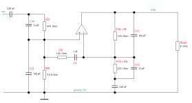
The (unreflected) recommendation leads to what? That was my question. It also leads to the same time constants, i.e. to a frequency-compensated divider,You should swap C11,C12
3900Ohm * 12pf = 46.8n sec
470Ohm * 100pF = 47n sec
but, the desired time constant was greater than 390n sec!
👍agreed - no need to exaggerate - it's only audio!
of course.


Actually, there are two with just fingers that you missed.
It’s called washing your dishes before you wash your dishes (So what does the dishwasher do?)
It’s called washing your dishes before you wash your dishes (So what does the dishwasher do?)
The side banter is all very well, but I would like to get back to the relentless analysis of the circuit in question.
For example, we could ask ourselves what ft the “reviled” Darlingtons must have as a minimum, so that we no longer criticize this (or similar) point!
HBt.
For example, we could ask ourselves what ft the “reviled” Darlingtons must have as a minimum, so that we no longer criticize this (or similar) point!
HBt.
Guaranteed minimum values are:
beta > 500
fT > 4MHz
This should be completely sufficient for an audio amplifier in the power range below 50 watts. So why do we like to criticize the transit frequency so much these days?
beta > 500
fT > 4MHz
This should be completely sufficient for an audio amplifier in the power range below 50 watts. So why do we like to criticize the transit frequency so much these days?
Because one can get better - a lot better - these days.
Even in the days when you could only get the fT and beta benefits in the first stage of an EF2 it was worth doing. The whole output stage is better behaved if the drivers are faster than the outputs.
Even in the days when you could only get the fT and beta benefits in the first stage of an EF2 it was worth doing. The whole output stage is better behaved if the drivers are faster than the outputs.
Guaranteed minimum values are:
beta > 500
fT > 4MHz
This should be completely sufficient for an audio amplifier in the power range below 50 watts. So why do we like to criticize the transit frequency so much these days?
Those darlingtons are good as long as you dont extract more than 2.5-3A, wich is enough for up to 30-35W/8R at most,
on 4R you are limited to 20W if you want to keep the same distorsion as 30-35W/8R, above 2.5A H3 distorsion start to rise
sharply and this can be countered only by using two pairs of devices, or better, implementing pre drivers, wich render the whole
thing non economical all while giving up the simplicity of integrated drivers
That s why they should be relegated either to these powers or for guitar amplifiers where the presence of an high H3 is eventualy
a desired feature, actually for a Hifi amp a pair of 2N3055/MJ2955 behave better assuming BC141/161 are used as drivers,
preferably the 141-16 and 161-16 because of their superior gain.
- Home
- Amplifiers
- Solid State
- 20WPA