Okay, so that we don't get too bogged down, I won't ask any more rhetorical “why” questions.
To summarize, the points of criticism raised are nothing more than marginal (albeit factual) observations. In the context of the simple structure and measured against the functional result, they slowly become lost.
All points apply almost equally to the AB100 proposal, but the ETI470 (represented here by the equivalent 20WPA) design is intended to address the “TIM or TID” issue of the time in the simplest way possible.
So the question is: does it do this?
#
Anyone interested in the subject of PSRR and the different +/-Rail Rejection can read chapter 9 “Power Supplies and PSRR” in the D.S. Compendium - or think for themselves.
There are almost countless commercial solution examples (from the last five decades) for a problem that only needs to be registered, i.e. taken into account in the subsequent implementation. In the first step, the principle, the core of the pure amplifier, its inherent ability to deal with an inadequate power supply is (for the time being) of secondary importance.
Absolutely correct!
#
If I also introduce a cascode, such as RAILS separated from the load circuit, I not only isolate (shield) ... well, then I also achieve dream values with regard to the point criticized here.
We all know how that works - and above all, Dieter Burmester knew this.
Let's not forget:
the ETI 470 proposal was designed and conceived as a simple DIY module.
Can it live up to the TIM claim?
kindly,
HBt.
To summarize, the points of criticism raised are nothing more than marginal (albeit factual) observations. In the context of the simple structure and measured against the functional result, they slowly become lost.
All points apply almost equally to the AB100 proposal, but the ETI470 (represented here by the equivalent 20WPA) design is intended to address the “TIM or TID” issue of the time in the simplest way possible.
So the question is: does it do this?
#
Anyone interested in the subject of PSRR and the different +/-Rail Rejection can read chapter 9 “Power Supplies and PSRR” in the D.S. Compendium - or think for themselves.
There are almost countless commercial solution examples (from the last five decades) for a problem that only needs to be registered, i.e. taken into account in the subsequent implementation. In the first step, the principle, the core of the pure amplifier, its inherent ability to deal with an inadequate power supply is (for the time being) of secondary importance.
+1More accurately, the lower the amp s PSRR the more everything depends on the PSU.
Absolutely correct!
This is precisely the feature of the entire Amplifier.In this form that s a voltage amplifier, but not in the case of Self amp,
To be precise, it is the ratio between the R7 and the output resistance of the input stage (of the LTP) ... currents are impressed here.on your schematic the collector load define
the gain along with the emitter load
Precisely, and in the case of the current mirror as a collector load in conjunction with the obligatory emitter degeneration resistors, we want to avoid an asymmetrical load as far as possible.while in the case of our discrete 741 the gain is defined by the IPS loading
That's exactly how it is, it's a completely different concept /story. Incidentally, the example you cite achieves an exorbitantly higher OLG then the 20WPA.and the
VAS input and output impedances, that s why the addition of this transistor, TR12 in Self s schematic, is so beneficial
as it decrease the IPS loading all while increasing the VAS input and output impedances and hence the IPS and VAS gains.
#
If I also introduce a cascode, such as RAILS separated from the load circuit, I not only isolate (shield) ... well, then I also achieve dream values with regard to the point criticized here.
We all know how that works - and above all, Dieter Burmester knew this.
Let's not forget:
the ETI 470 proposal was designed and conceived as a simple DIY module.
Can it live up to the TIM claim?
kindly,
HBt.
20WPA Version 1.1

HBt.
We could certainly try that out, maybe switchable to /between GND or to/ the base electrode.Your version has higher loop gain (45dB).
The solution is to get rid of R7. Instead, load the voltage amplifier with a resistor to ground.
Ed
HBt.
You're right - and thank you for the reminder about the coupling possibilities of interference. A point that is probably often forgotten or simply neglected.There s no mistake, here a transient simulation with 1V pk 100Hz injected in each rail,
this amount to -31.4dB,
exactly what is displayed at 100Hz in the frequency domain simulation.
They surely used a regulated PSU for the tests, otherwise they couldnt even have measured the amp noise,
I have offered the following simulation results for the negative rail in question:
PSRR-neg/
-37dB without R23 and C16 or other filtering
(up to -93.3dB with R23 and C16, at higher components)
-46.7dB without R7 (the same with R7 as load to GND)
(up to -102.95dB with R3 and C16, at higher components)
#
Obviously, the design should always mitigate the evil power supply side by feeding the entire preamplifier with a regulated power supply, here the negative rail and in the AB100 (from Nelson P.) the positive rail. Or take Douglas Self's well-known (but regularly forgotten!) solution suggestion to heart; an additional winding or an auxiliary voltage, another mains transformer ..!
In terms of R7, I can imagine that -10 extra dB might make a difference if an amplifier is humming annoyingly on the power supply side - but here they don't really make an elementary difference.
With 2 * 2 * 15mF charging capacity, and a sporadic peak load of 40W, i.e. a rather short-time discharge, with a peak-current of 2.2A -> there will be no disturbing ripple voltage on the rails (for a noticeable time).
But,
thx for the reminder - it is basicly a important case, mostly overlooked.
regards,
HBt.
🙂

20WPA Version 1.1
View attachment 1370466
We could certainly try that out, maybe switchable to /between GND or to/ the base electrode.
HBt.
This schematic unfortunately change nothing to the whole picture, THD and IMD will still be very high because the VAS
is extremely non linear and a high IPS current is of no help.
Guess that the designer believed that the VAS input current being negligible in respect of the IPS standing current would reduce
the global non linearity but it just dont work like this, actualy increasing the VAS input Z would not only yield the same result
in respect of IPS current loading but it would also increase the VAS gain and hence linearity once the loop is closed.
Anyway those Otala inspired designs rarely, if ever, produced convincing results, one of the few was the symmetrical
differential from SGS and still, with a classic miller compensation and some components values being changed
it was performing much better.
Despite the given and actually flawless function - by this I mean solely the fact that the amplifier can drive various loudspeakers easily and that completely effortless listening is made possible - it is somewhat sad when viewed in the light (i.e. analytically or even relentlessly).
With all the many abstruse design proposals from 1975 to 1990++, I now suspect nothing more than the attempt of a deliberately manipulative counter-current with the pseudo-predicate “high-end” or “low TIM” in order to set itself apart from really impeccable circuit topologies (and their correct dimensioning).
To be honest, I still don't understand these movements (and their arguments). Questions of faith! Nothing more.
#
If we look at my monos simply as a black box without knowing the contents, then we can't complain. With the text of the article and the circuit in mind, unanswerable questions arise -> it's crazy, and unfortunately set in stone.
HBt.
This illustrates very nicely what I am trying to express: in the text we read exactly the opposite. Strange; as is the story with the asymmetry in the current sinks of the IP stage. They should optimize something unknown, but what?THD and IMD will still be very high because the VAS
is extremely non linear and a high IPS current is of no help.
I also find the TIM, or TID specification, as an academic calculation value strange. With a calculation value, I always automatically ask for the calculation method.
IMD can be related to linearity, that is the output/input characteristics is not equal to a constant or rather it deviate
too much from a quasi constant.
What is called TIM is actually slew rate limitation, that is the inability of the amp to slew the signal fast enough,
that s obviously what these designs were adressing, but they didnt adress the gain linearity mentioned above,
quite the contrary, they just achieved speed but without any precision, that is the amp is slewing, uselessly, faster
but just to settle at the wrong output value.
I can repeat the measurements on this amplifier in mid-November at the earliest and then reveal them here, but it won't be possible before then.
If these results should be of any interest to a reader, I will be happy to start various measurement reports - so that I don't forget, a little practice doesn't hurt in these things.
Are there any special requests that I can fulfill without having to take the monos apart /dismatle?
greetings,
HBt.
If these results should be of any interest to a reader, I will be happy to start various measurement reports - so that I don't forget, a little practice doesn't hurt in these things.
Are there any special requests that I can fulfill without having to take the monos apart /dismatle?
greetings,
HBt.
I understand very well what's behind it, which is why I love different time functions for quick tests. If you can already spot anomalies here, then you already know “what kind of junk” is on the table.IMD can be related to linearity, that is the output/input characteristics is not equal to a constant or rather it deviate
too much from a quasi constant.
And at least one (or several) two-tone test.
The stupid thing is that we have a broadband system with a really good audio amplifier in front of us - according to the classic doctrine, the THD should be sufficient.
🤔
Attachments
Please audio measurements - audio forum;-)If these results should be of any interest to a reader, I will be happy to start various measurement reports - so that I don't forget, a little practice doesn't hurt in these things.
Are there any special requests that I can fulfill without having to take the monos apart /dismatle?
Special requests:
Do you have the version 1.1? Then rebuild to version 1, step by step, and listen to every step, and tell
a) if difference,
b) describe the difference,
c) grade the difference (subjectiv, no problem)
Then:
C3 > 100 uF
remove K14 and K15
replace K10, K11 and K3, K4, K8 per resistor
replace K9 (BD139) per BD441;-)
replace the remaining K12, K13, Darlingtnos, per transistors - do not forget to adjust;-)
If you have gotten to enjoy audio engineering and gaining audio experience, we could continue;-)
And always listen carefully after each step, and always do the steps:
a) difference audible?
b) difference describeable (and describing)? And, if you like,
c) graduate the difference.
With your supposed education you don't want to misinterpret LF-amplifiers as audio-amplifiers (I predict, this LF-amplifier is not even suitable to drive a motor in audio, whether for record players, CD players, cassette players - the hearing would detect it as unsuitable, because distorting, noisy - compared to a clean working one;-)
@cumbb
I'm talking about such primitive things as the transformation of the time domain into the frequency domain - or stuff like that. I would never talk about audio engineering here, but about measurement technology.
I have no idea whatsoever about your kind of auditory /hearing, alternately soldering and listening, development of electronic signal processors /"alternative Schaltungen".
And of course I no longer take things apart /dismatle just to feel like a seven-year-old child explorer again.
Even if the topic is exciting and I don't want to deny your unbridled enthusiasm for tinkering, I'm not going to emulate you. However, I will be happy if you report on your experiences here in an understandable way. It doesn't hurt if we take a step towards our readers.
I would even go so far as to advise you to have your possibly final conversions regularly inspected by specialists. Alternatively, get yourself an oscilloscope and a modern measuring system. I can only advise you to do this, no matter what unpleasant things may come to light in the objective measurement results.
If you get my drift,
HBt.

Psst
I would never dare to publish anything without measurements on the real object at hand.
I'm talking about such primitive things as the transformation of the time domain into the frequency domain - or stuff like that. I would never talk about audio engineering here, but about measurement technology.
I have no idea whatsoever about your kind of auditory /hearing, alternately soldering and listening, development of electronic signal processors /"alternative Schaltungen".
And of course I no longer take things apart /dismatle just to feel like a seven-year-old child explorer again.
Even if the topic is exciting and I don't want to deny your unbridled enthusiasm for tinkering, I'm not going to emulate you. However, I will be happy if you report on your experiences here in an understandable way. It doesn't hurt if we take a step towards our readers.
I would even go so far as to advise you to have your possibly final conversions regularly inspected by specialists. Alternatively, get yourself an oscilloscope and a modern measuring system. I can only advise you to do this, no matter what unpleasant things may come to light in the objective measurement results.
If you get my drift,
HBt.
Psst
I would never dare to publish anything without measurements on the real object at hand.
"Was sind Audio-Messungen?"Please audio measurements - audio forum ;-)
What are audio measurements, which descriptors and methods can you name?
My ear, nose and throat specialist strongly advises me not to believe that I can still hear properly. Ears are therefore ruled out as a means of measurement.
#
Joking aside,
which measurement should I carry out for you?
Special requests:
(...)
Then:
C3 > 100 uF
remove K14 and K15
replace K10, K11 and K3, K4, K8 per resistor
replace K9 (BD139) per BD441 ;-)
replace the remaining K12, K13, Darlingtnos, per transistors - do not forget to adjust ;-)
If you have gotten to enjoy audio engineering and gaining audio experience, we could continue ;-)
"übrig bleibt" After your slimming diet remains:
if I have understood you correctly?
A little detour, “I like magicians like Dan D'Agostino, for example”. We should compete with the greats - and stop doing exercises to consolidate the first basic lessons.
#
From a forensic point of view, you can of course dig up corpses - the undead live longer, as we all know.
In Hell I'll be
HBt.
#
From a forensic point of view, you can of course dig up corpses - the undead live longer, as we all know.
In Hell I'll be
HBt.
Last edited:
Solution to the riddle:
Garbage of this kind only works to a limited extent, or not at all !

So it's better not to take the user Cumbb's ideas seriously, however sweet they may be. The illustrative example can be driven up to 6Vpp, with a distortion level of no less than 3%.
And all this with 40W electrical losses.
Unfortunately, you can't win a flower pot with it - it never works like that. Perhaps I didn't interpret the stroke of genius correctly and deliberately misinterpreted it.
Only the stars know that.
Bye,
HBt.
Garbage of this kind only works to a limited extent, or not at all !
So it's better not to take the user Cumbb's ideas seriously, however sweet they may be. The illustrative example can be driven up to 6Vpp, with a distortion level of no less than 3%.
And all this with 40W electrical losses.
Unfortunately, you can't win a flower pot with it - it never works like that. Perhaps I didn't interpret the stroke of genius correctly and deliberately misinterpreted it.
Only the stars know that.
Bye,
HBt.
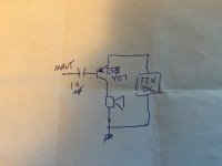
But you do get sound, and it is “clear”. Clear as in not all “staticky”. That itself is often considered “success”. This was the first amp I ever “built” that met the above criteria. Two parts, plus a battery and a speaker. I had literally no understanding how or why it worked. The only reason it DID was imperfections in the germanium transistor - excessive ICBO.
Attachments
Oh dear!
Far be it from me to tease any inventor, I like quirky characters.

But let's think of it as a kind of “regulars' table chat”, cheerful and boisterous over a few mugs of beer.
This specimen of my mean soul works in the simulator right away. Completely useless components such as the BD139, 140 & TIP3055, 2955 are used. 0.8Adc is quickly reached as the initial quiescent current ..!
At full scale the THD remains at about 1%. If we were to spin this flower pot further, we would end up with the well-known throw of Mr. Hiraga ---> this is no coincidence!
tbc
Far be it from me to tease any inventor, I like quirky characters.
But let's think of it as a kind of “regulars' table chat”, cheerful and boisterous over a few mugs of beer.
This specimen of my mean soul works in the simulator right away. Completely useless components such as the BD139, 140 & TIP3055, 2955 are used. 0.8Adc is quickly reached as the initial quiescent current ..!
At full scale the THD remains at about 1%. If we were to spin this flower pot further, we would end up with the well-known throw of Mr. Hiraga ---> this is no coincidence!
tbc
Last edited:
Dear reader,
please don't try this crazy and stupid stuff, build yourself a well-known Class B Blameless Amplifier (exactly according to D. Self's specifications) - that's my recommendation. You can also put stories like Class ABBA or Double Cross to one side with a clear conscience.
HBt.audio
please don't try this crazy and stupid stuff, build yourself a well-known Class B Blameless Amplifier (exactly according to D. Self's specifications) - that's my recommendation. You can also put stories like Class ABBA or Double Cross to one side with a clear conscience.
HBt.audio
If you take that circuit I “invented” and put in a SILICON transistor, and only made judgement based on how it “sounded” one would come to the conclusion that germanium is good and silicon sounds horrible.
And all of it based on incomplete understanding. That is either where cumbb is cumbbing from, or he IS making fun of us. It really is hard to tell.
And all of it based on incomplete understanding. That is either where cumbb is cumbbing from, or he IS making fun of us. It really is hard to tell.
- Home
- Amplifiers
- Solid State
- 20WPA