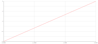
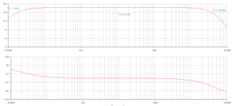
A view with a magnifying glass, so to speak; Vout=f(V_in), static.
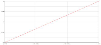
And that doesn't look bad at all, does it?
Cutoff;
with a load of 10Ohm, only one (single) Darlington (Ic).
And that doesn't look bad at all, does it?
Cutoff;
with a load of 10Ohm, only one (single) Darlington (Ic).
Attachments
I built this amp in about 1980/81. I replaced the original TIP devices with MJE15003/4 TO3 devices. At the time, the TIP devices had a bad rap. I used it for years but when I opened it up shortly before dumping it and getting a Marantz PM6800 (Philips used to own Marantz and I got a £500 cheque every 2 years to buy whatever I wanted in the Philips staff shop. It went on audio every time 🙂 ) I noticed R17 on both channels was burnt - I assume it had oscillated or I had somehow fed HF into the amp. Other than that, I never had problems with it. As for the Marantz, it ended up going to a family member when I started doing my own.

R17 is 4.7Ohm (approx. 2W resulting metal film type),I noticed R17 on both channels was burnt - I assume it had oscillated or I had somehow fed HF into the amp. Other than that, I never had problems with it.
in the original proposal, four 22Ohm resistors are connected in parallel, i.e. 5.5Ohm (formed from R25,26,27,28 each 1W types), ... actually these should not necessarily burn, but who knows today what the reason for this was?
#
The first original used:
2N4923
2N4920
2N3906
2N5400
for the limiter MPS6515
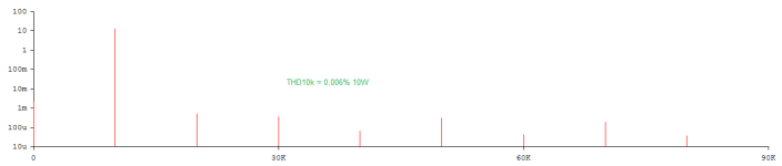
Just a few quick simulation results,
while the planet Krypton (i.e. ostripper ;-) ) is still asleep.
I think the results on the real DUT as real measurement results were better - the Klirr spectrum was definitely dominated by k2 ... oh, who knows exactly - and what's the point? The amplifier is absolutely not a bad one, I like it.
#
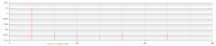
I like measurements on the object, tangible and real.
best regards,
HBt.
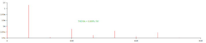
while the planet Krypton (i.e. ostripper ;-) ) is still asleep.
I think the results on the real DUT as real measurement results were better - the Klirr spectrum was definitely dominated by k2 ... oh, who knows exactly - and what's the point? The amplifier is absolutely not a bad one, I like it.
#
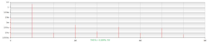
I like measurements on the object, tangible and real.
best regards,
HBt.
Attachments
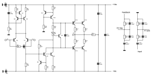
Another anomaly in hbtaudio's circuit is the capacitors in the voltage divider are reversed. The voltage dividers would have the same ratio at all frequencies if C11 and C12 were interchanged, and C13 and C14 were interchanged. This looks like a mistake, but given the design's weirdness, I am not sure.
Ed
Ed
You have to remember this amp was designed more than 45 yrs ago. Mainstream solid state amp design was still fumbling around. I think it’s a great exemplar of the state of the art in 1980 and mine was ok. Let me add, I knew very little about how to compensate an amp in those days! 🙂
By 1980 this design was more than obsolete, JVC s AX7 and AX9 were released in 1979, with triple serial and
cascoded diferential with the VAS one using a current mirror, non switching and error correction EF3 OS,
this ETI wasnt even up to the ultra classic Tanberg 1040 from 1974 wich was used as basis for a lot of DIY designs.
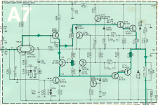
Tanberg 1040 amp part schematic is below :
cascoded diferential with the VAS one using a current mirror, non switching and error correction EF3 OS,
this ETI wasnt even up to the ultra classic Tanberg 1040 from 1974 wich was used as basis for a lot of DIY designs.
Tanberg 1040 amp part schematic is below :
Attachments
Last edited:
Let me try to recapitulate the history of this little amplifier:
In the summer of 2019, I decided to test this perhaps strange-looking construction proposal and made a PCB. Of course, it was clear to me “what I was playing with here”.
Due to the pandemic, there were various delays and dramatic changes - in short, I was severely affected. Nevertheless, I wanted to complete the project reasonably well, basically this amplifier was to be used as the core for a higher-level error correction.
But life always turns out differently than you think.
I tested the rudimentary function and found (according to my handwritten notes) frequency and level-dependent oscillation tendencies on the positive signal edge of the exciting signal.
With the “killer capacitor” C3 (original nom.) of 470nF, the amplifier was quietened down, but I didn't like this wooden hammer method, among other things for the reasons already mentioned here by @EdGr and others. I applied a defined bandwidth limit and simply tried out various scenarios on the object.
As always with the trial and error principle, you never improve stability this way!
In the end, the compensation scheme was clear - but in the confusion of the corona lockdown and other circumstances, the frequency-compensated voltage divider that was actually intended was, Ed assumes quite correctly, a very stupid calculation error, an error that caused no damage whatsoever. For these reasons, the networks look as I have posted them here (deliberately without indicating the actual error - on purpose!).
The inputs of the differential point (Q1,2) have identical impedances plus the real connection via the series connection of 100 Ohm + 1 nF... crazy, but this entire complex network keeps the system stable (and of course always the Zobel at the output).
#
Oh, actually it would be nice if we could get to the bottom of the matter "correctly" (as engineers usually do). From a purely hobbyist's point of view, I say: it obviously works.
Last edited:
Yes, that's true 👍.with triple serial and
cascoded diferential with the VAS one using a current mirror, non switching and error correction EF3 OS,
The circuit likely worked because the C11/C12 reversal introduced lead compensation at 410KHz.Oh, actually it would be nice if we could get to the bottom of the matter "correctly" (as engineers usually do). From a purely hobbyist's point of view, I say: it obviously works.
BTW, I have never ventured beyond one pole (and no zero) frequency compensation.
Ed
The other elephant in the room, that I didn’t even see at first, is R7. It introduces local feedback to the VAS. It reduces the amount of global feedback to the point where it’s stable (more so even then the VAS’s Cob). A little lead compensation is then all thats required. It also linearizes not only the VAS, but the output stage as well by reducing the driving point impedance. Driver device (internal to the darlingtons) speed matters less, and this keeps crossover distortion down. Amps that do this often have “iron fist” bass because even if global feedback is lost due to clipping the output impedance remains low. The speaker’s Qtc remains near its design value and the box doesn’t ring any more than it normally does. That doesn’t matter unless you’re driving the bejeezus out of it, but it’s something many of my amps are subjected to.
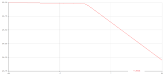
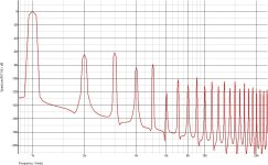
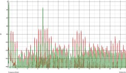
There s a 13 transistors count, now let s use only 8 out of these and re arrange it to yield something comparable
to the Tanberg above, just enhance the VAS with no current mirror and compare the IMD at same power, say 40W/8R.
Since this ETI is supposed to have low transient IMD it should have an even better behaviour with the classic
and not really transient 400Hz + 7kHz 4/1 ratio test that was ubiquitous during the 70s, but alas, it seems that the designer
just got the contrary of what he was seeking by using abnormaly high currents in the IPS s 15mA and VAS s 32mA,
all while suggesting to bias the OS at an unexpectedly lowish 25mA.
So the 13 transistors ETI is the one with the red curve and the infinitesimaly enhanced 10 transistors Tanberg 1040
is displayed in green, of course the original Tanberg doesnt behave, and by far, as well as its enhanced version,
but it would use only 7 transistors including a darlingtons OS.
Attachments
The question I always ask myself when I look at vintage amps like this is: could I design a better amp with the knowledge I had in 1980. The answer is invariably no, I could not. So these designs aren’t junk. They are representative of the general state of amplifier design at the time. We have the benefit of 45 yrs of accumulated knowledge, most it gleaned from people much smarter than us.
The only exception I’d make is some of the Elektor designs where chasing lower distortion became more important than stability - the worst design mistake IMV.
YMMV. 😊
The only exception I’d make is some of the Elektor designs where chasing lower distortion became more important than stability - the worst design mistake IMV.
YMMV. 😊

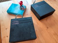
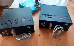
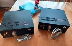
A little bit dusty, but that's how my monos look.
Fire up those babies! (and take/post some measurements)
You should swap C11,C12
Ok, nowadays one present ourself with a you-tube-video, where you talk a lot (mostly without substance), and so on - but I have absolutely no desire to do that.Fire up those babies! (and take/post some measurements)
I can only repeat myself:
- I test very extensively, which includes, among other things, all standard measurements
- I am not a documentation fetishist, i.e. handwritten notes are sufficient for myself, or rather I can remember what, how, where and why ..!
- I refer you to my posting #29
- my lifetime is also limited ... so if you can't wait, you have to become active yourself.
I use each of my amplifier; currently the MF-A1, which is available for purchase , a NAD C300 and the incredible DUAL CV121. When these two monos (20WPA) will be used again (or serve as a DUT just to play with my meters)? I can't say at the moment, two construction sites are still open, a) Beelzebub & Babe, b) the Stellema -> alias 25Watt Krill (see Steve D.) project.
Incidentally, ideas are just spraying daily out of my brain.
HBt.
- Home
- Amplifiers
- Solid State
- 20WPA